

 Completed
Multifunctional current and voltage detection usb_hub
PRO Multifunctional current and voltage detection usb_hub
License
:CC BY-NC-SA 3.0
Description
As an electronics enthusiast, have you ever encountered this situation:
- The USB port of the computer is not supplied with enough power, and the parallel power supply is backfilled, resulting in the burning of the USB port of the computer.
- After soldering a board and plugging it in, the current USB port was overcurrent due to a short circuit in some other places (such as a backlight).
- I want to directly judge whether the board is welded by the boot current of the board.
- Connecting multiple USB devices allows you to easily turn off and open a USB port at any time.
That's right,The above is the pain point I encountered in the pit electronic production in the past two years,At present, my computer USB port can only output 200mA current,More than that's wrong,The probability is that it was burned by the inverted insurance.
So for my own hard needs, I made such a multi-functional USB HUB.
Showcase Video: https://www.bilibili.com/video/BV1LdtMe1E3S/
Main control part: ESP32S3 module, plus 4-inch 86-box touch screen as the interactive end.
Current and voltage acquisition part: 4 INA226 chips are used to collect 4 voltage and current channels respectively, and transmit them to the main control through the I2C bus.
USB HUB part: CH334R chip, 4-port USB hub chip.
Power supply part: support 12v DC IN and PD decoy power supply, PD decoy chip adopts CH224K.
Electronic switch part: SY6288CAAC 2A switch chip is used to control the VBUS of 4 USB ports respectively.
Others: 4 additional RGB lamp beads are added to display the current status of each USB port (as an atmosphere group)
The PCB is divided into core board and HUB board, which is convenient for replacing other screens or main controllers (such as strip screens) in the future.

The screen supports a variety of 4-inch touch screens, both independent touch and touch integrated support, all of which have been verified.
Individual touch. It's from Taojing Chi https://item.taobao.com/item.htm?ft=t&id=757571286108&spm=a21dvs.23580594.0.0.1d292c1bCTukzD
Single line. Bohu's 3.95 "LCD display 4" square screen Smart home RGB interface resolution 480*480+86 IPS box - taobao.com
The two screen initialization codes are different, and you need to modify the macros in the source code.
APP introduction
HUB

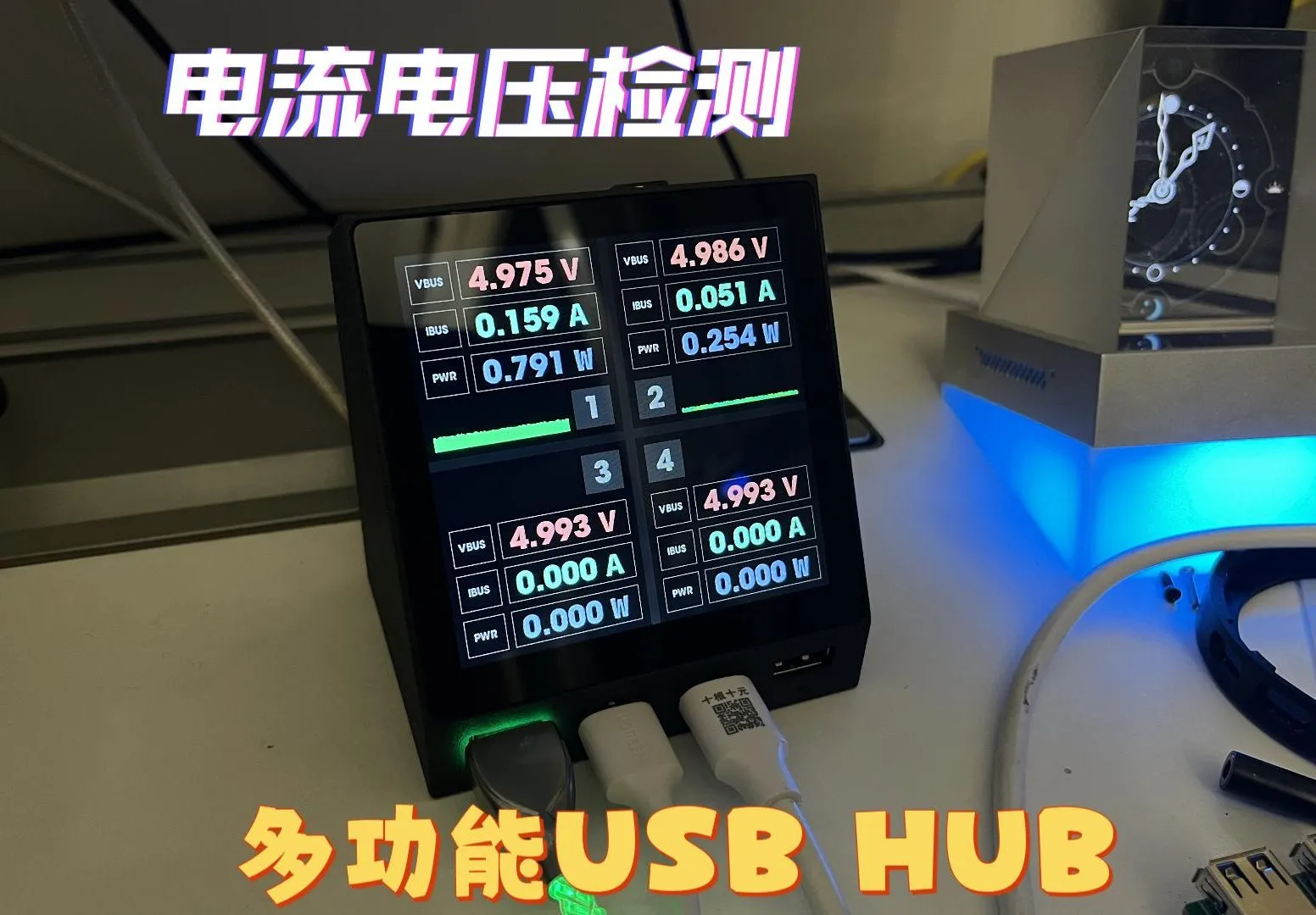
The screen display is divided into 4 areas (buttons), which are 1, 2, 3, and 4, corresponding to the 4 USB ports on the left.
Each USB port has 4 states:
1. Initialization fails, the button is not displayed at this time, and the RGB light under the port is not lit.
2. Normal, at this time, the button displays the current, voltage and power normally, and the RGB light under the port changes from green (0ma) to red (1000ma and above) according to the current current value.
3. Turn it off manually, the background color of the button is gray, and the RGB light under the port is dark white.
4. Overcurrent warning, at this time, the port number and current line graph turn orange-red, and the RGB light under the port is blue.
5. Over-current shutdown, at this time the port is disconnected and becomes a red background, if you want to re-open the port after the over-current is disconnected, you need to press the switch once to enter the manual shutdown state, and then press the switch again to enter the normal state, and the RGB light under the port is purple.
Swipe left to enter the settings page.

You can set the 4 current attributes of each port separately (alarm current, disconnect current, chart minimum current, chart maximum current), and switch the current setting port through the following number buttons 1 2 3 4.
Alarm current: When the port current reaches this value, it enters the overcurrent alarm state.
Disconnect Current: When the port current reaches this value, it enters the overcurrent shutdown state.
Chart Minimum and Maximum Current: Set the Y-axis minimum and maximum values of the current real-time line chart.
You need to press the tick of the virtual keyboard to trigger the save.
When you don't need current monitoring on a daily basis, you can switch to the following app and use the device as an atmosphere group.
AIDA64 secondary screen

This project obtains the information of AIDA64's RemotePanel, parses it, and displays it through its own UI.
Run AIDA64 on the computer and set the RemotePanel as required, and set the IP address of the computer on the device side (the two need to be in the same network segment), and you can use it.
Added unique gauge animations to CPU and GPU usage, and added a line chart effect over time.
Animation effects have also been added to the hard disk and memory usage.
Dynamic weather clock

The same weather clock as the previous project iCRT
The weather animation for this project comes from the HTC SENSE weather animation found online. HTC's mobile phone business has also been stopped for many years, if HTC tells me that I can't use it, please let me know, I will delete it as soon as possible.
The weather is updated every 3-5 minutes, currently from my Gaode API, if you have an API, you can apply for it yourself and then fill in your own use.
When the weather changes, there will be a silky transition animation.
In terms of clocks, it includes the display of the Gregorian calendar and the lunar calendar, including the display of common holidays and the 24 solar terms.
MJPEG playback
The latest and fastest SIMD decoding used in MJPEG decoding is the fastest decoding that can be done on ESP32-S3, which is 50-80% faster than ordinary decoding libraries such as JPEGDEC.
S3It's really hard to drive this large screen RGB,So MJPEG playback is about 12 frames,It is recommended to make some simple.
Picture album
It is to play the picture, and the switch has a gradient effect.
Swipe up all pages (except the settings page) to open the menu, and click the menu to enter the corresponding function.
On the settings page, click the arrow in the upper left corner to open the menu.
Fork Notes:
INA226 chip do not buy dismantling, the measured failure rate is more than 30%, as long as it is inaccurate or no display, it is recommended to change the chip, such as the LCSC is very stable, thank you for the support of the Stars plan.
In order to avoid 5V backfilling to the computer, do not connect DC IN and PD IN when burning, and unplug the USB after the flashing is completed. You can use your own USB1 port and 2 ports to directly connect the core board with a USB cable to burn.
Do not plug in the USB and DC IN of the PD at the same time, although the switch supports two switching, but there is no guarantee that there will be no short-circuit between the 12v and PD VBUS when the switch is toggled, so only one can be connected at the same time.
The electrolytic capacitor capacity of the USB port is not limited to 150uf, I solder 470 myself, I feel that the bigger the better.
PD decoy mouth of a few 0805 capacitance resistors can be used 0603, the reason why 0805 is used, one is copied, the other is that others say that the voltage of the large package is higher.
The price of shell 3D printing is about 26 yuan (9600 resin)
The fully functional source code of the USB HUB page is available for download here, and will be kept up to date.
If you want to make it, it is recommended to join the group to communicate, DIY communication group: 739444215
==============================================================
Supplemental updates
There are already many people who have done a good job (2024-11-05), and being able to come in handy is an encouragement to me.
Some common pitfalls were found during the reproduction process, and they are written here.
1. The touch screen I2C of the core board does not have a pull-up resistor, and the pull-up resistor is on the hub bottom plate, so if you only connect to the core board, there may be a situation where the boot card is there for a long time in the i2c initialization.
Solution: Plug in the extended version. Or modify the schematic diagram by yourself and add a pull-up resistor to the I2C SDA SCL two lines of the core board.
2. The sampling resistance is 10 milliohms, called alloy sampling resistance, which is 10 milliohms 10mΩ 10mΩ 10mΩ, R010, not 10M (mega) ohms, a few copies of the 10M ohm caused the system to think that the high current directly cut off the usb port.
3. If the corresponding INA226 address is not detected when booted, the corresponding button will not be displayed. Based on this, you can determine which chip has a problem (or is not soldered well)
4. If you don't plug in the power supply behind it, only plug in the USB that is burned, and the current of 3 or 4 ports is passed through the inductor, and it is normal for the value to be wrong.
5. The shell step file has been provided in the group, and you can modify it yourself if you need it.
Designed by 萨纳兰的黄昏 (from OSHWHub)
Link:https://oshwhub.com/planevina/multi-function-current-and-volta
Design Drawing
 Empty
Empty
Comment