Editor Version ×
recommended

Pro Edition

free

Brand new interactions and interfaces

Smooth support for design sizes of over 3W

devices or 10W pads

More rigorous design constraints, more

standardized processes

For enterprises, more professional users

Std Edition

Easy to use and quick to get started

The process supports design scales of 300

devices or 1000 pads

Supports simple circuit simulation

For students, teachers, creators

Completed

PRO MakerLab Moon Light - based on ESP32-C3 controller

Moon Light - based on ESP32-C3 controller

Project tags

License

GPL 3.0

License: GPL 3.0

Mode:

Mode

Editors' pick

Editors' pick

  • 25
  • 0
  • 0
Update time: 2024-11-19 09:23:15
Creation time: 2024-11-19 02:39:31
Description

Description

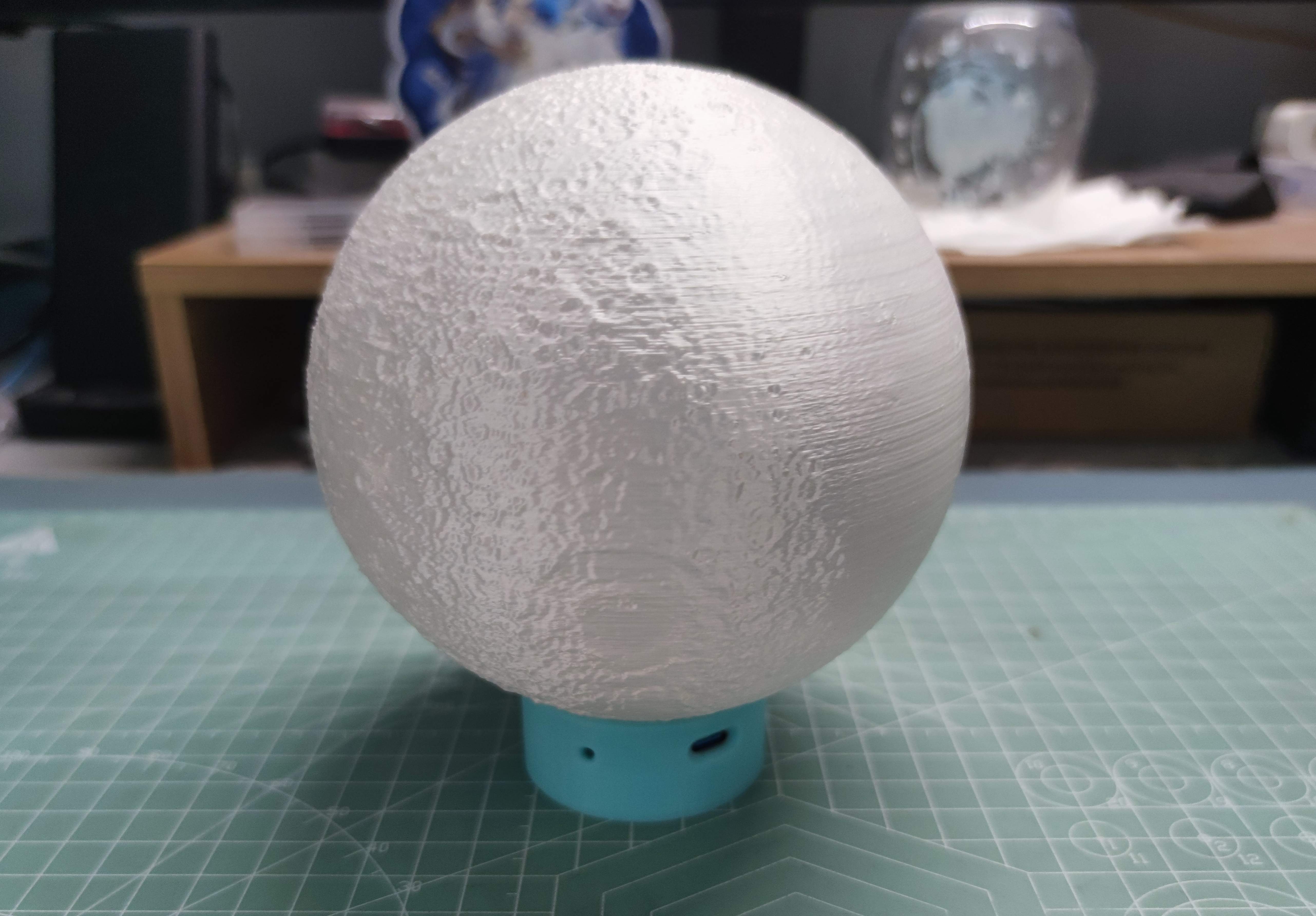
## Change log * 2024.01.20: Initially open sourced the project Ver2.4. * 2024.01.20: D1 can be removed and D2 short-circuited to get better power supply effect, waiting for the board to be printed again. ## 0. Model description Moon model link:[https://www.thingiverse.com/thing:3242080](https://www.thingiverse.com/thing:3242080) See the attachment for the flange and base models (the .SLDPRT file was created for SW 2020, please use version 2020 or above to open it ). **The lunar model needs to be offset a certain distance away from the normal direction of the thermal bed so that it has a certain reference plane mounting base. Then import the flange model and adjust it to the appropriate position so that the two can match well. Then merge the two models, or perform slicing directly (direct slicing will cause slight extrusion and overflow - routing duplication). Finally import the printer for printing. (See Figure 7 for printing effect)** It is recommended to embed M3 Tuba nuts/copper insert nuts into the flange holes to obtain better assembly results. The assembly screws are M3x26 ( It seems to be this parameter. I forgot about it when the model is not at hand. It doesn't matter if it is longer). (The moon model was printed a long time ago. The printer was not adjusted well at the time, and the layering was still very obvious.) ## 1. Effect display ![IMG_20240114_125813.jpg](//image.lceda.cn/pullimage/T4XTn2JWdIimCjbaS3HwD8F9zsHZcrpPwwVpsnYC.jpeg) Figure1 Actual picture 1 ![IMG_20231004_181830.jpg](//image.lceda.cn/pullimage/6lMFR3VBtta0PA6Y7B988i8fjOLf8iuTM7pWi9Cd.jpeg) Figure2 Actual picture 2 ![IMG_20240114_130129.jpg](//image.lceda.cn/pullimage/JMLoKohbPdQBS2LRKb9vR76JmL5GZQxCAcWpszIJ.jpeg) Figure3 Exploded view ## 2. Hardware design The controller needs to be as small as possible, so smaller components are needed. ### 2.1 MCU The MCU uses ESP32-C3-MINI-N4, which has a compact package and is easier to weld than QFN chips and has less peripheral resistance and capacitance. Built-in USB JTAG controller, you can directly use USB for programming, saving the cost and space of a USB-TTL chip (although the cost of ESP32-C3 is relatively high). It has WIFI and Bluetooth functions and can be connected to the Internet of Things platform. ### 2.2 Power management Power management needs to meet battery charging, system power distribution and control. The power architecture is shown in the figure below: ![20241119-104629.jpg](//image.easyeda.com/pullimage/ZSSSEYo7o3RCBxK1bHX6S48uAQ55rGxeQSSnd5oh.png) Figure4 Power Architecture Power management uses ETA6002. ### 2.3 Lighting That must have R! G! B! The more mainstream WS2812b lamp beads are used. It might be better to choose a model with a smaller package, but since I still have a lot of 5050 packages on hand, I just used it. Due to limited space, only two were put in, and the brightness was relatively limited. But, no one should use this thing for lighting, right? ### 2.4 Battery A polymer battery with size L35W30H10mm and capacity of 1000mAh was selected. Battery link:[https://item.taobao.com/item.htm?id=589740856789&spm=a1z10.1-c.w4004-22660760862.4.2c3e7f05jPE9V6&skuId=4258503775257](https://item.taobao.com/item.htm?id=589740856789&spm=a1z10.1-c.w4004-22660760862.4.2c3e7f05jPE9V6&skuId=4258503775257) (Khaki 103035-1000mAh) ## 3. Software design ### 3.1 Key function In terms of button functions, the software needs to realize: light switch, light brightness switch, and light color switch. This project uses the function reuse of a single button. They are: * KEY1 long press: light on/off * Double click on KEY1: switch the light color (5 preset colors) * KEY1 click: brightness switch (8 brightness levels) In terms of button function reuse,`OneButton library`is called to implement it. ### 3.2 WS2812b control WS2812b is a programmable RGB lamp bead that can be controlled through a program. This project uses `FastLED library`to achieve control. ### 3.3 Low power consumption & Internet of Things At present, the battery life is poor, and it can be used continuously for about 6 hours at the highest brightness state. Therefore, it is hoped that by allowing the MCU to enter a low-power state when idle, part of the MCU's power consumption can be reduced and battery life improved. After the Internet of Things, you can use the APP to check the status of the lights, control the status of the lights, or connect to the Mijia lights. These two features are currently still under development (gugu). ## 4. More pictures ![IMG_20240114_125949.jpg](//image.lceda.cn/pullimage/BDb8VLfI14GUi64QFYkzRoRfO4UeW1ajRLkpng4T.jpeg) Figure5 Actual picture 3 ![IMG_20240114_130339.jpg](//image.lceda.cn/pullimage/2A5GMzuV1ggNepYe5X2MyHxkOWsIDy9hIdKMQlAb.jpeg) Figure6 Actual picture 4 ![IMG_20240114_125916.jpg](//image.lceda.cn/pullimage/M0Ulp0KyHJ3a5622A7AQlppSxP3MWcVPeDp9hBZ8.jpeg) Figure7 Actual picture 5 ![IMG_20240114_130339.jpg](//image.lceda.cn/pullimage/qGIWxoaWFHmsvbTeHYn8jhlXiS6oi3yWacc9V2Fm.jpeg) Figure8 Actual picture 6 (this side is the Type-C interface and reset button - an ejection pin is required) ![IMG_20240114_130354.jpg](//image.lceda.cn/pullimage/eG2T4BPWFiJnzwTCTW019dYtkMFhs4RTM2iNkkwT.jpeg) Figure9 Actual picture 7 (this side is the multi-function button) ![IMG_20231004_163601.jpg](//image.lceda.cn/pullimage/JCmxJXSGFbUn1xEFb52PGtuirX3toemyasPmxV7E.jpeg) Figure10 Actual picture 8 ## Appendix ### Appendix 1: Source code ``` #include #include #include "OneButton.h" // FastLED #define NUM_LEDS 2 // Number of LED beads #define DATA_PIN 10 // The Arduino outputs control signal pins #define LED_TYPE WS2812 // LED light belt model #define COLOR_ORDER GRB // The order of red, green and blue leds in RGB lamp beads uint8_t max_bright = 255; // LED brightness control variable, the value can be used from 0 to 255, the larger the value is, the higher the brightness of the light band CRGB leds[NUM_LEDS]; // Set up light band leds // OneButton #define button1_Pin 5 OneButton button1(button1_Pin, true); // variable unsigned char status=0; // LED switch status unsigned char brightness=0; // Brightness state unsigned char colorStatus=0; // Color State List // function void click1() { if(status) { brightness+=32; FastLED.setBrightness(brightness); FastLED.show(); if(brightness

Designed by carele_i (from OSHWHub)

Link:https://oshwhub.com/carele_i/moonlight

Design Drawing

Design Drawing

schematic diagram
1 /
PCB
1 /
The preview image was not generated, please save it again in the editor.
Empty
Project Attachments

Project Attachments

Project Members

Project Members

Target complaint
Related Projects
Change a batch
Loading...

Comment

Add to album ×

Loading...

reminder ×

Do you need to add this project to the album?

服务时间

周一至周五 9:00~18:00
  • 0755 - 2382 4495
  • 153 6159 2675

服务时间

周一至周五 9:00~18:00
  • 立创EDA微信号

    easyeda

  • QQ交流群

    664186054

  • 立创EDA公众号

    lceda-cn