 Completed
Modular Tablet Computer -QPad
PRO Modular Tablet Computer -QPad
License
:GPL 3.0
Description
Project Description
Modular industrial tablet: QPad.
Modular design: The core board and functional modules can be replaced according to needs, and it is compatible with commercial modules such as Raspberry Pi and Orange Pi as core boards.
Applicable industrial scenarios: on-site debugging, communication testing, sensor data collection, monitoring terminals, trajectory recording, etc.
The current version is V1.0, which inevitably has some shortcomings. We plan to update the project in the future, so you can collect it and continue to pay attention. Videos of various application scenarios will be updated on station B in the future.
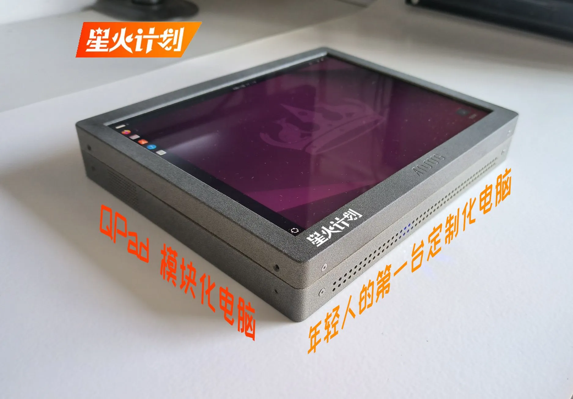
After asking for it for a long time, I finally got the 3D printed one out. (Due to the wall thickness and material, the shell is slightly deformed. Ignore it for now. The CNC shell will be followed later.)

Figure 1 - Windows version
(the first printing version, the white material is a bit translucent, and was later changed to a darker color.)

Figure 2--Ubuntu version
(The second time I printed the shell, the effect was much better.)

Figure 3 - Top interface diagram
(the main application scenario of the screen backlight switch is that when used as a server, the screen can be actively turned off)

Figure 4 - Schematic diagram of the back
(the antenna area designed for the CNC shell is not used, because the CNC did not pass, and I was too lazy to change the model later, so I printed it according to the CNC model.)

Figure 5--Overall renderings
Function module:
1. GPS+BD positioning module (track record and other GIS products)
2. NBIot communication module (Internet of Things product testing)
3. 4G communication module
4. WiFi and wired network (standard configuration)
5. Serial port module (supports TTL, RS485/422/232 levels, necessary for industrial debugging)
6. 2.4G wireless module (multi-node aggregation function when used as a data collection terminal)
7. Storage expansion module (expand large-capacity hard drive to store data)
Open Source Agreement:
GPL.
Project Related Functions
1. Display: Finally, a cost-effective 9.7-inch IPS screen with 2K resolution is used. I believe everyone already knows what kind of screen it is.
2. Core board: The core board is compatible with Raspberry Pi, Orange Pi and other single-board computers as the core board (if you have time, adapt to TSPi in the next step).
In order to meet the performance requirements, it was decided to support a maximum of 12x12 motherboards. This design is compatible with NUC6i5 motherboards.

3. Function module:
Regarding the interface of the expansion module, the author has thought about it for a long time. At first, I wanted to refer to an interface similar to PCI-E. However, since the module function is not that complicated, using too many Pin interfaces is a bit overkill, and then I want to customize a private interface...
After thinking about it, I suddenly found the USB flash drive in the corner of the table. Why not use the USB interface?
Therefore, all the extended functions of this design use the USB interface, which is both convenient and simple.
Divide all functions into two categories: high speed and low speed. The high-speed one uses USB3.0, and the low-speed one uses USB2.0.
USB3.0 module:
- Storage expansion module
- RJ45 network port expansion module
- USB3.0 extension
USB2.0 module:
- GPS+BD positioning module
- NBIot communication module
- 4G communication module
- Serial port module
- 2.4G wireless module
4. Excessive modularization will appear cumbersome, and excessive integration will appear inflexible. To balance the two, we decided to integrate some commonly used (necessary functions) functions, including the following functions:
- RJ45 network port expansion
- M.2 hard drive expansion
- The screen driver part uses DP to EDP direct drive, which effectively saves circuit complexity. If you use the HDMI interface, you can use the NCS8803 module from last year's Spark project.
- The battery management part uses the LM25116 chip to reduce the battery voltage to 12V for system use. In addition, the screen backlight specifically uses a TD1583 chip.

- USB3.0 expansion and USB2.0 expansion interfaces, 4-way 2.0 interfaces are provided on the left side, and 4-way 3.0 interfaces are provided on the right side. This module is used when the number of USB core boards used is insufficient.

- Then there are the non-essential functions, which can be extended through modules:
- The GPS module adopts the ATGM332D module of Zhongke Microelectronics. The ATGM332D series module adopts a size of 12.2×16mm. It is based on the sixth generation multi-system GNSS SoC single chip AT6668 of Zhongke Microelectronics. It supports Beidou-2 and Beidou-3 (B1I and B1C), GALILEO, GPS/QZSS/SBAS, GLONASS and other satellite navigation systems.

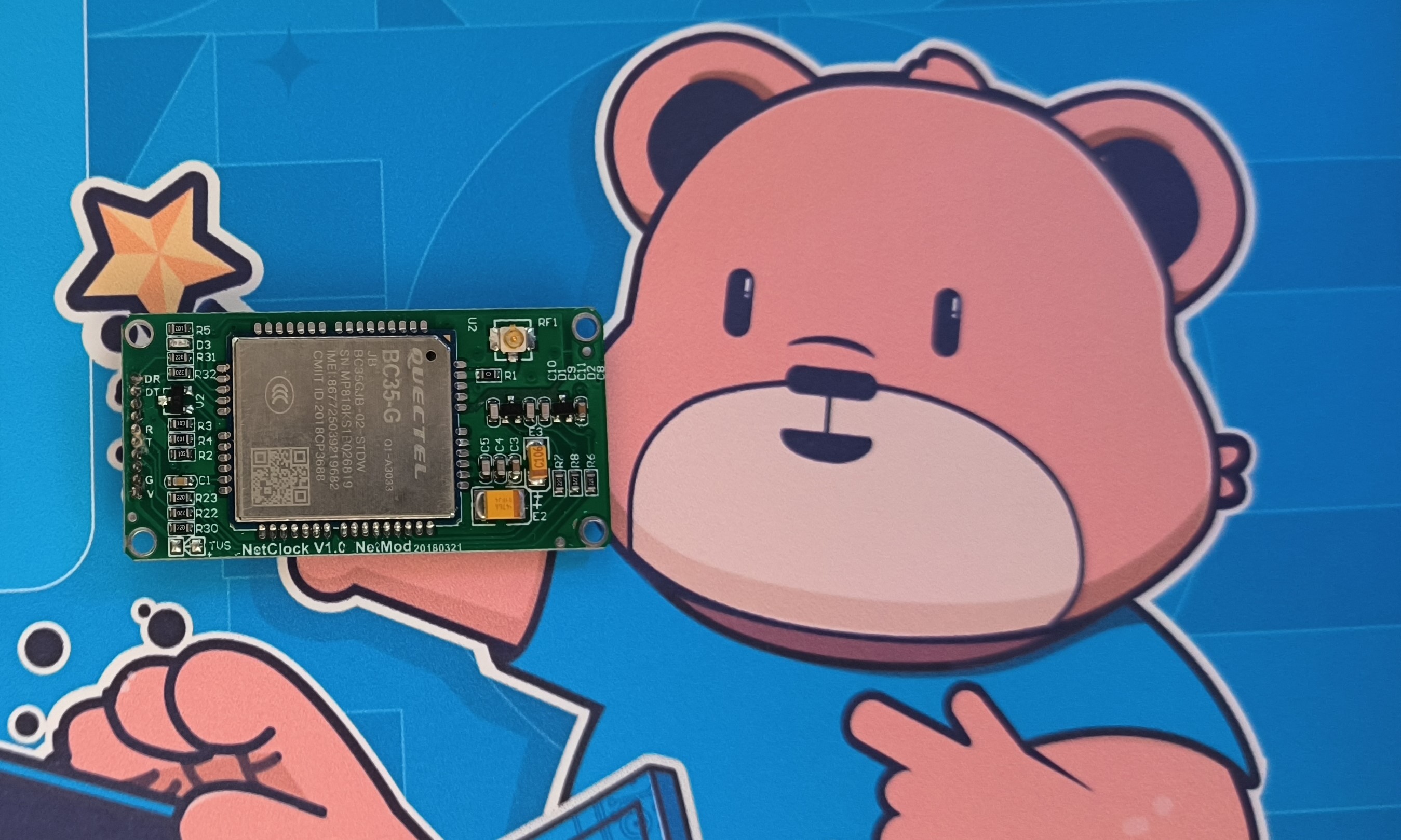
- NBIot communication module (to avoid repeated development, this module uses the previous project module and is connected to the system through the serial port.)

Project Properties
This project is made public for the first time and is my original project. The project has not won any awards in other competitions.
Project Progress
March-April: The project system architecture is established, the specific implementation plan and chip selection of each module are clarified, and the appearance of the product is initially determined. (completed)
May-June: Circuit design and sample testing. (As of May 15, the circuit design has been completed and the application for proofing and testing has been completed)
July: Modify and improve the circuit part based on testing.
You can't walk by the river without getting your shoes wet.
The first version of the free SMT was a surprise. Most of the functions were designed on one board. The structure was really difficult to detach when designing the casing (the size of the battery was ignored during planning).
Moreover, the 3.0HUB chip was soldered by myself. After three solderings, I still couldn't get it right, so I gave up on this version and redesigned separate small boards. You can choose which boards to use according to your needs.

Debugging process:
The picture below uses NUC6 as the core board (why not use the latest NUC12? Because funds are limited/(ㄒoㄒ)/~~Are there any sponsors...)
The miniDP to DP video cable in the picture cannot be bought of the right length. I soldered this one myself. It took me several hours. I forgot to consider the length of the plug when measuring the length (+1 for carelessness), so it still looks a little bit longer. A little longer.
NUC6 draws less than 2A of current during normal use (not fully loaded), which is relatively power-saving.
The current will exceed 2A when installing Ubuntu.
Heat dissipation problem:
First, the radiator directly contacts the CNC aluminum shell to increase the heat dissipation effect. In the picture, because of the 3D printed shell, the radiator is attached to the metal backplate of the screen.
The second is to plan to add a 4cm fan on the casing to suck air outward.
In addition, the core board has rich USB interfaces, so the USB extension version is not installed yet.
Space issues:
The limit is to install the NUC motherboard as the core board. You can see that the space in the picture is basically full, and only a few USB expansion modules can be installed in the remaining space.
However, if you use a Raspberry Pi single-board computer as the core board, there is still plenty of space. You can refer to the following pictures.


The picture below is a schematic diagram of the assembly using Orange Pie as the core board. It can be seen that the space is very generous.

August: Finalize the appearance of the product according to the assembly situation, design the shell and print it.
Design Principles
1. The power supply part uses 4 strings of lithium batteries for power supply. The main transformer converts the lithium batteries to 12V for use by each module. The topology is shown in the figure below:

The parts that consume a lot of power, such as the screen backlight and M.2 hard drive power supply, use 12V to directly transform to the required voltage.

[12V main power supply circuit]
Other power supplies are converted independently.

[Power supply circuit for each voltage - part]
Software Description
1. Visual debugging program (python) connected to the IMU6050 module -----IMU6050-serial.py

2. LiDAR driver source code under ROS under Ubuntu system --- xv_11_laser_driver-hydro-devel.zip
3. GPS module debugging software---U-center (Tested at an indoor window, the star collection effect is not good.)

4. Onboard microcontroller program on the IMU-6050 module (self-made) ---IMU6050 - C0.1.rar
Physical Display
Frontal photo.

It's a little thick, but it can accommodate the maximum thickness of the NUC.

From right to left on the top are the main power switch, core board on/off switch, screen switch (the screen can be turned off separately when used as a server), and charging interface.

Built-in speakers, one on the left and one on the left.

Renderings

Renderings

Renderings

Design considerations
1. When using NUC as the core board, a fan must be added to the air outlet to assist heat dissipation. It is recommended to use a 4x4x0.7 fan.
2. When the USB interface board is connected to an external high-power electrical device, connect the 12V power supply of the module and disconnect the 0 ohm resistor at the 5V of the USB port.
3. In order to be compatible with high-performance NUC motherboards, the thickness control of this design is not ideal.
4. The 8pin of the serial port chip CH340N on the GPS module needs to be connected to a 0.1uF decoupling capacitor.
Designed by qzc13457 (from OSHWHub)
Design Drawing
 The preview image was not generated, please save it again in the editor.
 Empty
Empty


Comment