

 Completed
Mini walkie-talkie based on BK4802: Lingxiang LXB
PRO Mini walkie-talkie based on BK4802: Lingxiang LXB
License
:CERN Open Hardware License
Description
The program is for learning purposes only and is subject to applicable laws and regulations.
Regulations of the People's Republic of China on Radio Administration
Notice on issues related to the management of public walkie-talkies
For commercial use, it is necessary to retain the boot splash screen, PCB author and project name silk screen, and indicate the source: https://oshwhub.com/qwqoffice/lxb-nano-radio-based-bk4802/
QQ group: 1002613160
2024-12-05 Update:
1. 702040 battery and 102040 battery, the merchant has changed the capacity identification from 650mAh and 1200mAh to 500mAh and 800mAh, but the actual capacity is the same, and the original capacity is a false standard.
Design background
I still remember that on May 22 this year, McDonald's went on sale to the sauce machine, and when I saw it, it was already out of sale, as an electronic enthusiast, how could I be wronged by this, so I thought about making one myself (although I also bought it later)
I saw other people's orders on the Internet, and summarized the following shortcomings of McDonald's for sauce machines:
1. Automatic shutdown in 10 minutes.
2. The frequency cannot be changed, and it is easy to connect with others (note: the regulations only allow the public walkie-talkie to fix a frequency, but if you DIY, you still hope to cover all the frequency bands supported by the chip)
3. Use No. 7 battery, which cannot be charged.
Then what I did by myself must be to correct all these shortcomings, so there is this project.
Here, I would also like to thank McDonald's for letting us know BK4802, a domestic RF chip, which is highly integrated and only needs a simple peripheral circuit to complete the production of a wireless transceiver.
Open-source protocol
CERN Open Hardware License
Project properties
This project is the first public and is my original project. The project has not won an award in another competition.
Github link
https://github.com/qwqoffice/lxb-nano-radio-based-bk4802
Bilibili link
https://www.bilibili.com/video/BV1QbUyYrEXz/
Model introduction
LXB: Standard version, 29mm speaker, with display.
LXBM: Mini version, 21mm speaker, with display.
LXBE: Lite version, no speakers, no display.
Feature Highlights
Knob on/off/volume adjustment (LXBE only)
It can be connected to 3.5mm headphones.
Supports back clips and lanyards
At the same time, it supports 3D printing shell/acrylic shell
Supports built-in up to 99 frequencies
Comes with Windows and Android management tools
Detailed instructions for use and technical documentation
Physical display
Front

Back

Left

Right

Top

Attach the sling clip

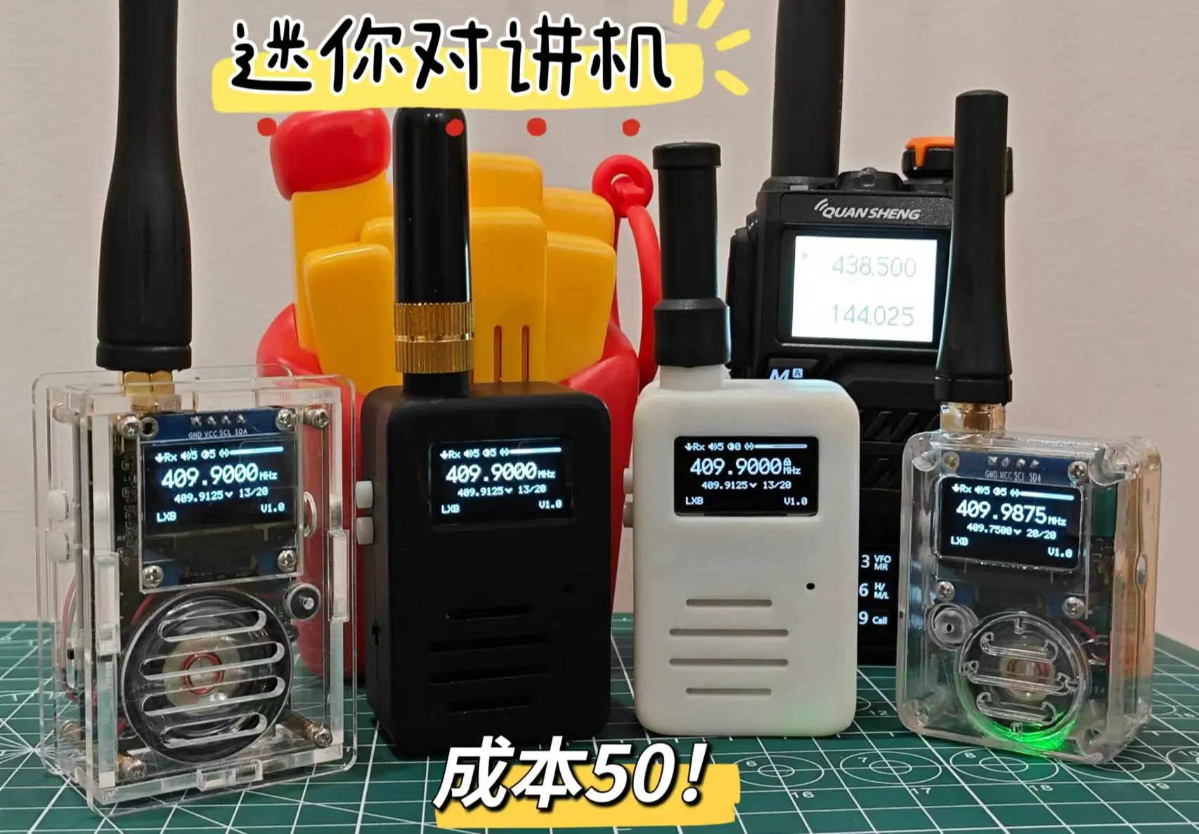
Compare Izumi Sheng UVK5

Compare McDonald's walkie-talkies

The LXBE Lite has not yet completed the design of the shell.


Hardware design

The selection of single-chip microcomputer, based on the original idea of transmitting instructions to the MCU through the serial port to perform certain operations, and BK4802 is an I2C communication protocol, the key needs a PTT key and a SET key, then the MCU needs to support serial port and I2C, except for the previous at least 2 IO as the key input. Since I haven't done many projects and don't know which MCUs to choose from, I use the selection function in Lichuang Mall, filter the above conditions and ascend by price, the first one is STC8G1K08. Later, due to the lack of space in the program, the STC8G1K17 was used instead. When designing the LXBE version without screen and speakers, the function of the knob to adjust the volume required the ADC to obtain the potentiometer voltage, so it was changed to STC8G1K17A (LXB and LXBM can still be used STC8G1K17 version without ADC)
LDO piece, the initial version used AMS1117-3.3V (only knew this at the time), the actual use found that as long as the speaker was turned on, the single-chip microcomputer would be reset, and then it was found that the reason was that there was a power mutation when the speaker was turned on, LDO could not bear it, the voltage was reduced to about 2.4V, and the single-chip microcomputer triggered a low-voltage reset. Later, refer to McDonald's plan and use Nanjing Weimob's ME6230C33M5G.
In terms of lithium battery charging management, the commonly used TP4056 was selected, and the charging current was set to 0.5A.
The lithium battery supports two specifications: 702040-650mAh or 102040-1200mAh.
USB to serial port, choose the most basic model CH340N in the CH340 series, to meet the use.
In terms of power supply, the single-chip microcomputer, screen, and 4802 all use LDO power supply, and CH340 uses USB direct power supply, because the STC microcontroller needs to detect the serial port device first when programming the program, and then power on the single-chip microcomputer after clicking to download in order to burn normally.
The speaker sound, stepping on a big hole, that is, the volume is always not up to the same level as the McDonald's walkie-talkie, I have tried to buy speakers of various specifications, modify the settings of 4802, and even directly remove the McDonald's speaker and install it to me, to no avail. Later, it was found that it was a problem with the sound cavity, when we debugged the hardware, we often put the speaker directly outside, and then pick it up and put it on the ear to listen, so that the sound emitted by the speaker is very small, and a sound cavity is needed to emit a normal level of volume, and the shell is a good sound cavity, but it is inconvenient to install it into the shell when debugging, and the easiest way is to make a fist with your hand and cover the back of the speaker to form a simple sound cavity, and the sound will be expanded N times immediately.
The addition of the 3.5mm headphone jack can be clear intercom in a noisy environment, and an 8pin headphone jack is used here, which allows you to physically disconnect the built-in speaker and microphone when the headphones are plugged in, and switch to the speaker and microphone of the headphones to achieve the effect of automatic switching, and at the same time I designed a toggle switch, which can be switched to use the built-in microphone even if the headphones are plugged in.
In terms of screen, a 0.96-inch OLED screen is used, which is of moderate size, and it is also an I2C protocol, and the RF chip shares the IO port.
The antenna interface uses a standard SMA male connector, which can directly use the walkie-talkie antenna on the market.
For the impedance matching part, there is no time to make up for RF-related knowledge, so you can simply refer to some tools on the Internet to calculate the impedance matching circuit, and RF bosses are welcome to improve.
Software design
Key gesture detection
There are only two function buttons designed in the project, but it is hoped that most of the core functions can be completed directly on the walkie-talkie, reducing the dependence on the host computer software.
In fact, it is also possible to use different keys to connect resistors with different resistance values, and then use the ADC to read the value to judge the range to distinguish which button is pressed, and whether it is pressed at the same time, but the single-chip microcomputer was originally selected without ADC function, so this method was not used.
I see someone else on the Internet dealing with it like this, detecting the press, delaying for a period of time, and then still detecting that the key is pressed, you can judge that the key is artificially pressed, not because of jitter, but this kind of recognition can not be done for long press, because for example, if I want to press and hold for 1 second and then execute, then I have to delay for 1 second, during which other codes cannot be executed, if I need to read the status to the screen in a loop, then the state cannot be updated on the screen during the delay period. Therefore, I changed the way to design a timer, save the milliseconds of the single-chip microcomputer running to a variable milliseconds, save the current running milliseconds to a variable down_start when the key is pressed down_start - milliseconds > 1000 , and judge each cycle, that is, the key has been pressed for more than 1 second, so that the cycle will not be blocked, so that the single-chip microcomputer has the opportunity to perform other tasks.
char set_down = 0; // SET Whether to presschar set_long_down = 0; // SET Whether to press and holdunsigned long set_start = 0; // SET Press the start timeunsigned long set_long_start = 0; // SET Press and hold to press the start time
char ptt_down = 0; // PTT Whether to pressunsigned long ptt_start = 0; // PTT Press the start timechar ptt_long_down = 0; // PTT Whether to hold down or not
char set_ptt_down = 0; // Whether SET and PTT are pressed at the same timechar set_ptt_long_down = 0; // Whether to hold down SET and PTTunsigned long set_ptt_start = 0; // SET and PTT Press the start time
// Processing keyvoid HandleKey(){ // SET按下 if(set == 1 && set_ptt_down == 0 && ptt == 1) { set_ptt_down = 1; set_ptt_start = milliseconds; Refresh_Setting_Last_WakeUp(); }
if(set == 1 && set_ptt_down == 0) { if(set_down == 0) { set_start = milliseconds; set_down = 1; Refresh_Setting_Last_WakeUp(); } if(set_down == 1 && set_long_down == 0 && milliseconds - set_start > 1000) { // SET long press greater than 1000ms if(is_setting_mode == 1) { setting_index++; if(setting_index > 1) { setting_index = 0; } OLED_HideSettingIndex(); HandleWakeUp(0); } else { set_long_start = milliseconds; HandleWakeUp(1); } set_long_down = 1; } if(is_setting_mode == 0 && set_down == 1 && set_long_down == 1 && milliseconds - set_long_start > 300) { // SET Keep long pressing every 300ms set_long_start = milliseconds; HandleWakeUp(1); } } // SET release if(set == 0 && set_down == 1) { if(set_long_down == 0 && set_ptt_down == 0 && milliseconds - set_start > 30) { // SET press to keep it greater than 30ms if(is_setting_mode == 1) { if(setting_index == 0) { SetNextVolumeLevel(); } else if(setting_index == 1) { SetNextContrastLevel(); } Refresh_Last_WakeUp(); } else { HandleWakeUp(1); } } set_down = 0; set_long_down = 0; }
// PTT press if(ptt == 1 && set_ptt_down == 0) { if(ptt_down == 0) { ptt_start = milliseconds; ptt_down = 1; } if(ptt_down == 1 && ptt_long_down == 0 && milliseconds - ptt_start > 60) { // PTT press to keep the value greater than 60ms ptt_long_down = 1; HandleWakeUp(0); SwitchTx(); } }
// PTT release if(ptt == 0) { if(ptt_down == 1) { if(ptt_long_down == 0 && milliseconds - ptt_start > 30) { // PTT press to keep it greater than 30ms HandleWakeUp(0); } ptt_down = 0; ptt_start = milliseconds; } if(ptt_down == 0 && ptt_long_down == 1 && milliseconds - ptt_start > 60) { // PTT is held down for more than 60ms and released for more than 60ms ptt_long_down = 0; SwitchRx(); } }
// Cancel while pressing if(set_ptt_down == 1 && set == 0 && ptt == 0) { if(is_setting_mode == 0 && milliseconds - set_ptt_start <= 1000) { // Handle the SET button to lock or unlock SwitchLock(); HandleWakeUp(0); } set_ptt_down = 0; set_ptt_long_down = 0; } if(set_ptt_down == 1 && set_ptt_long_down == 0 && milliseconds - set_ptt_start > 1000) { // Enter setup mode if(is_setting_mode == 0) { EnterSettingMode(); } else { ExitSettingMode(); } HandleWakeUp(0); set_ptt_long_down = 1; }}
Potentiometer ADC debounce
In the model LXBE, I refer to the design of Quansheng UVK5 walkie-talkie and use a potentiometer with a switch, which can be used as a power switch and a volume adjustment knob at the same time. When the knob is turned, the ADC value read in a loop changes, and then the BK4802's received volume register is controlled to achieve the effect of volume adjustment. In practice, the ADC value will inevitably have jitter, that is, if you turn the knob in one direction, ideally the value should always increase or decrease, but in fact, the value will suddenly become larger, and then suddenly return to normal, at this time, a debounce algorithm is needed to smooth the value. The debounce algorithm is not static, but needs to be processed according to the actual jitter. In my case, my debounce scheme is as follows: divide the ADC value change into 3 states, increase, decrease, and constant, and when the same state lasts for 3 or more times, the value can be judged as a valid value, otherwise it will be discarded.
char adc_prev_direction = 0;int adc_direction_count = 0;int adc_prev_values[3] = {0, 0, 0};int adc_stable_value = 0;
void HandleVolADC(int value){ int diff; char direction; diff = value - adc_prev_values[0]; // orient if(diff == 0) { direction = adc_prev_direction != 0 ? adc_prev_direction : 0; } else { direction = (diff > 0) ? 1 : -1; } // Determine whether the direction is the same if(direction == adc_prev_direction) { adc_direction_count++; } else { adc_direction_count = 0; } // If the direction is the same the degree is greater than or equal to 3 if(adc_direction_count >= 3) { adc_stable_value = adc_prev_values[2]; } if(adc_direction_count > 3) { adc_direction_count--; } // update adc_prev_values adc_prev_values[2] = adc_prev_values[1]; adc_prev_values[1] = adc_prev_values[0]; adc_prev_values[0] = value; adc_prev_direction = direction;}Using the values of the above debiting algorithm, the glitches are significantly reduced compared to the original data.

AT command system
AT instructions are often used for communication between various terminals, and are a simple communication protocol, the core of which is the parsing and extraction of strings.
void HandleATCommand(char* command){ char* params; char* cmd; char* equalSign; char* end; char* paramArray[MAX_PARAM_COUNT]; int paramCount; char* token; unsigned int result;
// Instruction format is AT+{instruction}[= parameter 1, parameter 2,...] if(strncmp(command, "AT+", 3) == 0) { cmd = command + 3; equalSign = strchr(cmd, '=');
// Remove \r\n at the end of cmd end = cmd + strlen(cmd) - 1; while(end > cmd && ( * end == '\r' || * end == '\n')) { * end = '\0'; end--; }
if(equalSign != NULL) { * equalSign = '\0'; // Replace the equal sign with a string terminator to extract the command params = equalSign + 1;
// analytic parameter paramCount = 0;
token = strtok(params, ","); while(token != NULL && paramCount < MAX_PARAM_COUNT) { paramArray[paramCount++] = token; token = strtok(NULL, ","); }
if(strcmp(cmd, "EEPR") == 0) { result = IapRead(HexStringToValue(paramArray[0])); HexToString(buffer, result, 2); UART_SendStr(buffer); UART_SendNewLine(); } else if(strcmp(cmd, "EEPW") == 0) { for(i = 1; i < paramCount; i++) { IapProgram(HexStringToValue(paramArray[0]) + i - 1, HexStringToValue(paramArray[i])); } UART_SendOK(); } else if(strcmp(cmd, "OLEDC") == 0) { OLED_WrCmd(HexStringToValue(paramArray[0])); UART_SendOK(); } else if(strcmp(cmd, "OLEDD") == 0) { OLED_Set_Pos(atoi(paramArray[0]), atoi(paramArray[1])); OLED_WrDat(HexStringToValue(paramArray[2])); UART_SendOK(); } } // If there is no equal sign, it is processed as a command with no arguments else { if(strcmp(cmd, "RSTR") == 0) { UART_SendOK(); IAP_CONTR = 0x60; } else if(strcmp(cmd, "TYPE") == 0) { UART_SendStr(MODEL); UART_SendNewLine(); } } } else { UART_SendError(); }}
Software design of the upper computer
Since the host computer software plan supports both Windows and Android platforms, I initially wanted to use Qt for cross-platform development, but in the actual development process, the progress was very slow due to the unfamiliarity with Qt. NET MAUI, and then found that there is still a big difference with C#, and finally gave up cross-platform and turned to the familiar C# for Windows development.
At present, the development of the Windows side has been completed, and the Android side is being planned.
Because the firmware has been designed with AT instructions, the host computer software only needs to use AT instructions to communicate with the microcontroller, and there is no need to develop another set of communication protocols.
The Windows side requires .NET Framework 4.8 or above, which is designed with a single exe file, which does not require installation and is easy to carry.
Device selection screen.

Main interface

Built-in frequency management interface

Shell design
3D printing shell and acrylic shell are designed with Solidworks, here I would like to thank the Solidworks desktop small screen shell design course provided by the UP master @阿奇设计分享 of station B, let me get started with Solidworks 0 basics, and successfully design the walkie-talkie shell in a short time, the quality of the course is very high, it is highly recommended that students who have the need to design shells for PCB learn it: https://www.bilibili.com/video/BV1DW4y1K7Ww/
Note: The design of the housing of the LXBE model has not yet been completed, please choose this model carefully.


A light guide pillar is a part that transmits LED light from a PCB to the surface of the housing. It is difficult to buy shape-matching light guide parts on the Internet, so you can only design them yourself, but the choice of material is another problem. I accidentally found that the 8001 material is printed in a translucent state, which is suitable for making a light guide column, the price is cheap, 2 yuan for a part, and the effect is not bad, refer to the figure below.

Cost estimates
| Material | Price |
| PCB | Free |
| OLED | 8.4 |
| lithium battery | 7.8 |
| BK4802 | 2.4 |
| CH340 | 1.5 |
| TP4056 | 0.1 |
| ME6230 | 0.3 |
| STC8G1K17 | 0.7 |
| SMA male | 3.2 |
| Headphone jack | 0.5 |
| LED | 0.1 |
| 21.25MHz crystal oscillator | 0.3 |
| Resistance capacitance | 1 |
| Pin header and female header | 0.5 |
| Screws copper pillars | 1.5 |
| switch | 1.1 |
| Speaker microphone | 0.5 |
| TypeC Socket | 0.1 |
| 1.25 line | 0.5 |
| 1.25 connectors | 0.5 |
| Shell | 14 |
| Antenna | 5 |
| Total | 50 |
Note: The above prices are unit prices and do not include shipping costs
The housing material is 9006.
Instructions for making it
First, select the model you want to make.
Note: The design of the housing of the LXBE model has not yet been completed, please choose this model carefully.
1. Place an order for PCB
The thickness of the PCB is 1.2 mm.

2. The next single component material
BOM has done most of the matching, you can place an order according to the BOM, the following components can not be matched, you need to place an order on Taobao separately:
Note: Do not buy the crystal oscillator according to the BOM, the BOM is 24MHz.
BK4802:http://e.tb.cn/h.T1kYHqjRTh5sovf?tk=AP6o3HgxwrJ,Need to consult the merchant to send SOP16 package
OLED(GND,27.3*27.8mm):https://m.tb.cn/h.gmbY7lScoVBnXzm?tk=KS3p34kHjA1,Specification: 0.96 "white OLED module /4P
21.25MHz crystal:http://e.tb.cn/h.T1k1JMcjrETQYhp?tk=8LTv3HgyLB8
M2x4 screw:http://e.tb.cn/h.T1kbhRUNsYZSanB?tk=WTfw3HgDZne ,specification:M2*4(50个)316
M2x11copper column:https://m.tb.cn/h.gmbZUfpZVVaXGkz?tk=yHp434kJKN6,specification:M2*11[40]
1x4p:https://m.tb.cn/h.gmb0coOGh1UYSjb?tk=GV9034kJSrW,specification:1x4p 2.54mm In-line single bar Black (20 PCS)
Lithium battery (choose one of the two)
702040-500mAh:http://e.tb.cn/h.T1GCyFAzIppxgI7?tk=AKFv3HgApZZ
102040-800mAh lithium battery:http://e.tb.cn/h.T1OsjI7wbDHikXV?tk=gUyP3HSofGH
Antenna:http://e.tb.cn/h.TcUvGROK5kXIARI?tk=eotG3HTa6oF,specification: female, length and shape according to preference
Speaker (choose 21mm or 29mm depending on model)
21mm Speaker: http://e.tb.cn/h.T1EH5UadMajIY5G?tk=chnI3HSJzZn, Specification: Diameter 21mm 8 ohms 0.25W Small Speaker Plastic (5pcs)
29mm speaker:http://e.tb.cn/h.T1EH5UadMajIY5G?tk=chnI3HSJzZn,specification: diameter 29mm 8 ohms 0.25W small speaker plastic large magnet (5pcs)
Microphone:http://e.tb.cn/h.T1jNxztT7tjLG9s?tk=oeav3HStZdQ,specification: 52DB pickup without pin 6*5mm microphone (10pcs)
1.25mm line:http://e.tb.cn/h.Tc6ImjQ09ObZEIu?tk=fQlo3HSuDhr,Specification: 2P-single-head -10CM(30 pieces )
Purchase of enclosures using 3D printing:
M2x12 screw:http://e.tb.cn/h.TcOSLkVcTgVksvK?tk=09Uc3thSr7h ,Specification: M2*12(50 pieces)
Purchase using acrylic housings:
M2x8 screw:http://e.tb.cn/h.TcEApyQ8Wd4UoVZ?tk=pqDK3th7lFb ,Specification:M2x8[100pcs]
M2x14 screw:http://e.tb.cn/h.TcEApyQ8Wd4UoVZ?tk=pqDK3th7lFb ,Specification:M2x14[100pcs]
M2x7 copper column:http://e.tb.cn/h.Tcw06O1z4787SJA?tk=00mt3thRVkc,Specification:M2*7[40pcs]
M2x12 copper column:http://e.tb.cn/h.Tcw06O1z4787SJA?tk=00mt3thRVkc,Specification:M2*12[20pcs]
3. Place an order shell
Choose a 3D printed case or an acrylic case depending on your preference.
3D printed shell
Order platform: JLC 3D
Table 1: Detailed explanation of 3D printed shell files
| NO. | filename | Print parameters |
| 1 | No rounded corners V4_ the keys. STL | LEDO 6060 White is not polished |
| 2 | Back clip. STL | 9600 Matte White Grinding - Coarsely Ground |
| 3 | Light guide column with connecting rod V2.STL | 8001 translucent |
| 4 | Light guide block occlusion. STL | JLC Black is not polished |
| 5 | Walkie-talkie_21mm speaker_7mm battery_lower case_with back clip. STL | 9600 Matte White Grinding - Coarsely Ground |
| 6 | Walkie-talkie_21mm speaker_7mm battery_lower case_no back clip. STL | 9600 Matte White Grinding - Coarsely Ground |
| 7 | Walkie-talkie_21mm speaker_10mm battery_lower case_with back clip. STL | 9600 Matte White Grinding - Coarsely Ground |
| 8 | Walkie-talkie_21mm speaker_10mm battery_lower case_no back clip. STL | 9600 Matte White Grinding - Coarsely Ground |
| 9 | Walkie-talkie_21mm horn_upper shell. STL | 9600 Matte White Grinding - Coarsely Ground |
| 10 | Walkie-talkie_29mm speaker_7mm battery_lower case_with back clip. STL | 9600 Matte White Grinding - Coarsely Ground |
| 11 | Walkie-talkie_29mm speaker_7mm battery_lower case_no back clip. STL | 9600 Matte White Grinding - Coarsely Ground |
| 12 | Walkie-talkie_29mm speaker_10mm battery_lower case_with back clip. STL | 9600 Matte White Grinding - Coarsely Ground |
| 13 | Walkie-talkie_29mm speaker_10mm battery_lower case_no back clip. STL | 9600 Matte White Grinding - Coarsely Ground |
| 14 | Walkie-talkie_29mm horn_upper shell. STL | 9600 Matte White Grinding - Coarsely Ground |
Table 2: Models and corresponding parts to be printed.
| Loudspeaker | battery | Back clip | Print the number |
| 21mm | 7mm | Yes | 1、2、5、9 |
| 21mm | 7mm | No | 1、2、6、9 |
| 21mm | 10mm | Yes | 1、2、7、9 |
| 21mm | 10mm | No | 1、2、8、9 |
| 29mm | 7mm | Yes | 1、2、10、14 |
| 29mm | 7mm | No | 1、2、11、14 |
| 29mm | 10mm | Yes | 1、2、12、14 |
| 29mm | 10mm | No | 1、2、13、14 |
| No | No | - | LXBE has not yet been designed |
Select the specifications of the battery speaker back clip, find the number to be printed according to Table 2, and then find the file corresponding to the number according to Table 1, and place an order according to the corresponding parameters.
Among them, the main part of the shell, numbered 5~14, can be replaced with other materials according to your preference, and other numbers are recommended to use the recommended parameters to place an order.
The light guide column is an optional part, please see the front shell design part, if necessary, please place an order number 3 and 4.
Acrylic shell
Order platform: LCSC
Table 3: Models and corresponding drawings to be printed.
| loudspeaker | battery | Drawing files | Paper size |
| 21mm | 7mm | Drawings _21mm speakers _7mm batteries. DWG | 140*140mm |
| 21mm | 10mm | Drawings _21mm speakers _10mm batteries. DWG | 140*140mm |
| 29mm | 7mm | Drawings _29mm speakers _7mm batteries. DWG | 140*150mm |
| 29mm | 10mm | Drawings _29mm speakers _10mm batteries. DWG | 140*150mm |
Order parameters: transparent acrylic, drawing file name and drawing size see Table 3, conventional, no adhesive required, 2.5mm thickness, pure cutting without printing.
4. Welding
Most of the components are SMD, and it is best to use heat guns and solder paste for soldering, the following are the precautions:
1. The two buttons and TypeC interface need to be outside.
2. IC components, crystal oscillators, and LEDs need to pay attention to the direction, refer to the silk screen on the PCB.
3. The solder on the back of the TypeC interface should be flush with the PCB as much as possible to avoid hitting the battery.
4. The pin header of the OLED screen is beyond the screen plane, try to use needle-nose pliers to cut it off, so as not to affect the shell assembly.
5. The female and SMA male of the screen need to be flat and not crooked, so as not to affect the shell assembly.
6. The speaker is welded with 1.25mm wire, and the positive and negative poles are not distinguished (the copper sheet needs to be welded to both ends, and the error demonstration is in the figure)
7. The microphone is welded with 1.25mm wire, and the positive and negative poles need to be distinguished.
8. The lithium battery can be connected with a 1.25mm wire, and a section of heat shrinkable tube is used to cover it after the outer skin is manually connected.


5. Assemble
3D printed enclosure assembly
(1) Prepare the necessary items, as well as screwdrivers and tweezers.

(2) Use M2x4 screws*6 and M2x11 copper pillars*3 to fix the OLED screen (the copper pillar in the upper left corner is not installed)

(3) Flip down the switch to turn off the power, and then connect the lithium battery, speaker, and microphone.

(4) Put the lithium battery, the printed text down, into the lower shell, and fix the wire to the wire duct.

(5) Use tweezers to put in the button with the small bump up.

(6) Put in the PCB and adjust the wires of the speaker and microphone to the PCB grooves.

(7) If the light guide pillar is used, first combine the light guide column and the light guide pillar blocking parts, then pick up the PCB first, install the light guide pillar on the PCB, and then press and hold the light guide column to push the whole into the shell (here the light guide column is not required for the installation of transparent shell)


(8) Adjust the direction of the antenna interface, as shown in the figure.

(9) Put the speaker and microphone into the upper case, if it is loose, you can use glue to fix it.

(10) Close the upper and lower shells, leave a gap and adjust the wires inside with tweezers, and fix the shell with M2x12 screws*4 after closing.

(11) Attach the antenna, attach the back clip as needed, and complete the assembly.

Acrylic housing assembly
(1) Prepare the soldered PCB, screen, lithium battery, speaker, microphone, 3D printing buttons, acrylic shell, M2x4 screw*6, M2x11 copper pillar*3, M2x14 screw*4, M2x7 copper pillar*4, M2x8 screw*4, M2x12 copper pillar*4.

(2) Use M2x4 screws*3 and M2x11 copper pillars*3 to install the copper pillars that hold the screen in place.

(3) Flip the power switch down to turn off the power and connect the lithium battery, speaker and microphone.

(4) Use M2x14 screws*4 and M2x7 copper pillars*4 to attach them to the lower shell.

(5) Put in the PCB and put in the front case.

(6) Use M2x12 copper pillar*4 to fix the four corners of the PCB.

(7) Put it on the screen and fix it with M2x4 screw*3

(8) Put in the left, right, and back shells

(9) Place the speaker and microphone into the plywood

(10) Use tweezers to put in the button

(11) Cover the splint and upper shell and secure it with M2x8 screw*4. Attach the antenna and complete the assembly.

6. Burn the firmware
Method 1: Use STC-ISP to burn the record
(1) Download burning software STC-ISP:https://www.stcaimcu.com/data/download/Tools/AIapp-ISP-v6.94Y.zip
(2) Use a TypeC cable to connect the computer and the walkie-talkie, and pay attention to the data transmission function of the cable.
(3) Open the STC-ISP software, set the chip model as STC8G1K17-8PIN or STC8G1K17A-8PIN (according to the model you are welding), select 12.000MHz IRC frequency, set the EEPROM size to 2K, uncheck the erase user EEPROM area, and other default settings do not need to be changed.

(4) Click "Open Program File", select "lxb_1.0.hex" for LXB and LXBM, and select "lxbe_1.0.hex" for LXBE.
(5) Click "Download/Programming"
(6) Dial the power switch of the walkie-talkie upwards to power on the single-chip microcomputer, and the program will start to burn.
Method 2: Use a software upgrade tool to burn the record
The software upgrade tool is a programming software packaged by STC-ISP with pre-set parameters, so no additional settings are required.
(1) Use a TypeC cable to connect the computer and the walkie-talkie, pay attention to the cable with data transmission function
(2) LXB and LXBM open the file "lxb_upgrade_1.0_{chip model}.exe", and LXBE opens the file "lxbe_upgrade_1.0.exe"
(3) Click "Start Upgrade"
(4) Dial the power switch of the walkie-talkie up, power on the single-chip microcomputer, and the program will start to burn
7. Instruction manual


Boot
Turn the power switch upward, the device turns on, and the green power indicator lights up. Turn down the power switch to shut down the device and turn off the green power indicator.
Launch
Press the PTT key, the intercom is switched to the launch mode, the blue launch indicator light, at this time you can speak to the microphone, and the best distance from the microphone is 5~10CM. Release the PTT button, switch back to the receiving mode, and the blue emission indicator goes off.
Switch to the next frequency
Short press the SET key to switch frequencies in the built-in frequency cycle. After holding down the SET key for 1 second, switch the frequency every 300 milliseconds.
Locking frequency
Press the PTT and SET keys at the same time to enter the frequency lock mode. In this mode, the frequency cannot be switched by the SET key. Press the PTT and SET keys simultaneously again to exit frequency lock mode.
Adjust the volume and brightness
First, hold down the PTT and SET keys for 1 second at the same time to enter the setting mode. In the setting mode, long press the SET key for 1 second to switch the setting item, you can know the volume or brightness of the item being SET through the setting item indicator icon, and short press the Set key to change the current setting item. The volume and brightness range from 0 to 5. Hold down the PTT and SET keys at the same time for 1 second, or exit the setting mode without performing any operation within 5 seconds.
Connect headphones The walkie-talkie supports 3.5mm headphones connected to the International Standard (CTIA), and the interface definition is shown in the following figure. When the headset is inserted, the intercom automatically disconnects the built-in microphone and speaker, and uses the headset as the audio input and output. Microphone mode can be set to fixed mode, always use the built-in microphone, see the following section.

Restore the default settings
Turn the power switch down to turn off the device, press the SET button, keep the power switch down, turn the power switch up until "Settings restored" is displayed on the screen, the device is restored to the default Settings, then release the SET button.
Charge
Use the TypeC charging cable to connect the device to the charger, and the red charging indicator lights up to start charging. After full charge, the red charging indicator goes off. A 5V output voltage charger should be used to avoid damage to the equipment.
Microphone mode
Microphones work in two modes: Automatic mode: Use the headset microphone when inserting the headset and use the built-in microphone when removing the headset. Fixed mode: Whether or not the headset is inserted, use the built-in microphone to switch modes. After removing the cover, find the microphone mode lever located on the top right of the circuit board, and dial up to the mode fixed mode and downward to the automatic mode.

Manage built-in frequencies
By default, the firmware has 20 built-in public intercom frequencies ranging from 409.7500MHz to 409.9875MHz. To change the built-in frequency, you can use the accompanying software.
Supporting software
Walkie-talkies support connecting Windows and Android devices for built-in frequency management and more settings, use the browser open https://www.qwqoffice.com/product/lxb/ or scan the qr code for supporting software.

Technical parameters
| size | 63.3mm*40.8mm*25.7mm (LXB) 55.8mm*40.8mm*25.7mm (LXBM) Note: 1. Does not include antenna, clip and protrusion. 2. The thickness of the battery is 7mm, and the capacity is 500mAh. |
| weight | 62g |
| Battery capacity | 500mAh/800mAh |
| Input voltage | 5V |
| Transmit power | 10mW |
| Operating frequency band | 24~32、35~46、43~57、128~170、384~512 |
Technical Documentation
Instructions for attachments
-
lxb_firmware_src_1.0.zipWalkie-talkie firmware source code, keil project, the default compilation of LXB, LXBM model firmware, if you need to compile LXBE firmware, modify the 10th line of main.c, uncomment #define LXBE and recompile.
-
lxb_firmware_1.0.zipCompiled radio firmware.
-
lxb_upgrade_tool_1.0.zipSoftware upgrade tool for burning.
-
lxb_shell_3d_v1.zip3D printed enclosure STL file.
-
lxb_shell_panel_v1.zipAcrylic housing DWG drawings.
Designed by 幻想小籽 (from OSHWHub)
Link:https://oshwhub.com/qwqoffice/lxb-nano-radio-based-bk4802
Design Drawing
 Empty
Empty
Comment