

 Completed
Micro Deceleration Servo [the second small size of the whole network]
PRO Micro Deceleration Servo [the second small size of the whole network]
License
:GPL 3.0
Description
Project Description:
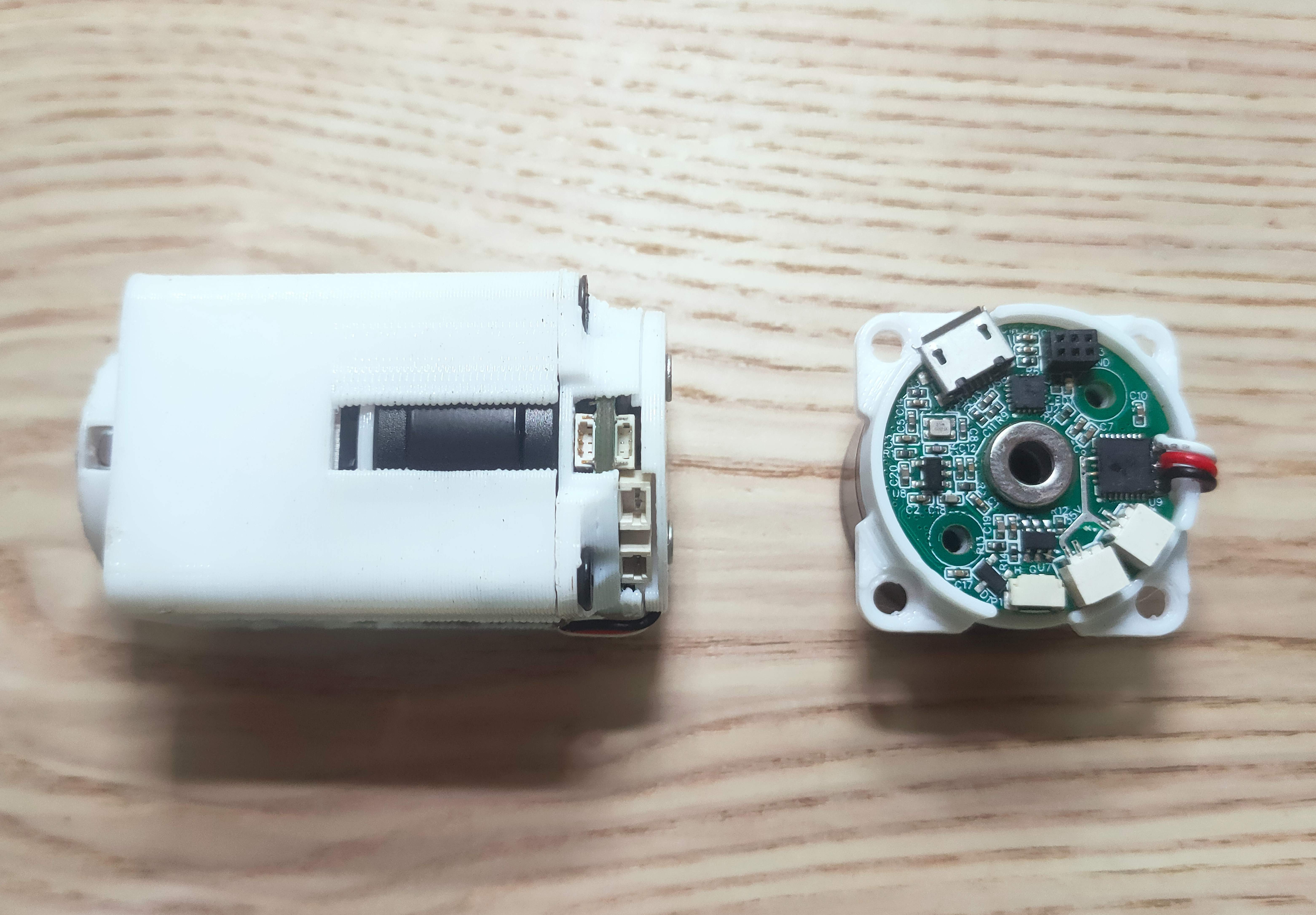
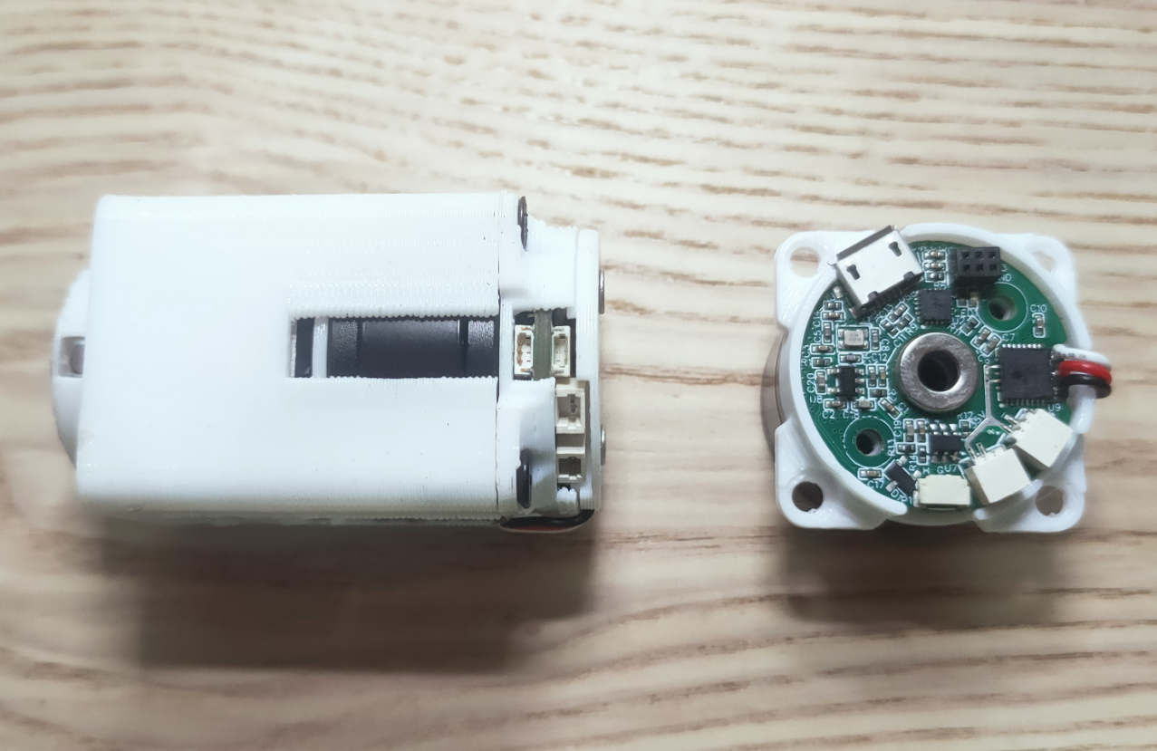
This is an open source micro deceleration servo for DIY enthusiasts. The overall size is 30*30*53mm . The reduction ratio of the self-developed reduction gearbox is 81, which can also be made into 9. The box body is composed of aluminum substrate parts processed by JLC and PC material 3D printed parts. Zero gap can be achieved through adjustment. The power source is the FOC driven hollow pan/tilt brushless motor model BM2916H. The size of this electric drive integrated hollow servo motor is φ29*25mm , and the PCB size is φ27mm , making it the second smallest size in the entire network. . The first and smallest motor is custom-made and cannot be purchased...
Video introduction URL: https://www.bilibili.com/video/BV1mF41127Bm/
Open source address: https://gitee.com/qiaoge_soruce/foc_micro_driver
This project open sourced the PCB, 3D model, hardware BOM, debugging documentation, aluminum substrate parts PCB and hand-rubbed FOC control program.
Open Source License:
GPL3.0
Circuit Description:
The main control uses STM32G473CCU6, the magnetic encoding uses MA730, and a second encoder interface is reserved. The motor driver chip uses MP6540, which supports low KV gimbal motors with a maximum current of 3A. 5Mbps dual can and dual power interfaces support serial connection of motors for easy wiring. The PCBA withstand voltage reaches 35V, the communication interface has anti-static and anti-surge protection, and has good stability.


Program Description:
The code is written in C language and Keil5 project files are provided. The motor current loop frequency is 20000Hz, and 3-channel current sampling processing makes the output power reach 100% (2-channel sampling cannot be 100%). The current loop uses Kalman filtering (low-side current sampling requires filtering), the speed loop uses phase-locked loop speed measurement data (phase-locked loop is equivalent to low-pass filtering), and the position loop uses magnetic ring offset correction data (magnetic ring installation offset and Magnetization offset can cause errors between electrical and mechanical angles). The code integrates automatic calibration angle algorithm, odrive anti-cogging torque algorithm, self-developed electrical angle prediction compensation algorithm (somewhat useful), magnetic ring offset scanning and other functions. The communication is modified using odrive's cansimple.
With the support of this series of algorithms, the minimum speed of the motor can reach 0.015rps or about 1rpm , and the position loop control accuracy is 0.05° .
Parameter setting is to connect the motor through USB and use letter-shell command line interaction, and the motor operating parameters are fed back through the serial port log. Because I can't write the host computer. . .


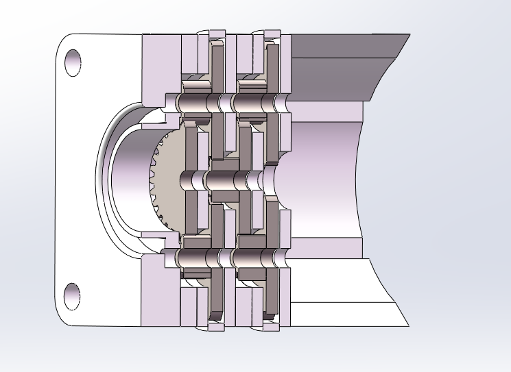
Reducer Description:
The self-developed spur gear reducer has reduction ratios of only 81 and 9. The 81 is suitable for a robotic arm, and the 9 is suitable for a mechanical dog. The key load-bearing components of the reduction gearbox are replaced by machine-processed aluminum substrates processed by JLC to reduce DIY costs. I couldn't find a suitable 0.4 mold 10:30 double-layer gear on the market, so I went to customize a powder metallurgy mold to get it (it was really hard work). The final iteration achieved almost zero backlash through jackscrew adjustment.
Attach video link: https://www.bilibili.com/video/BV1sw411M7gC/?spm_id_from=333.999.0.0&vd_source=e79120ea207c988af0666c51395bfd12
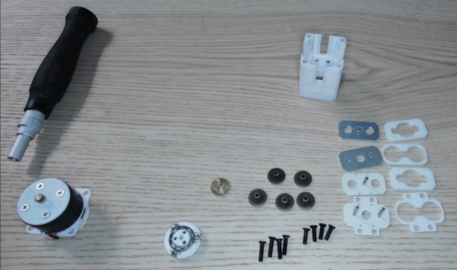

The insulation layer of the aluminum substrate is a Teflon layer, which is a very good self-lubricating material.
Installation Diagram:
Project Properties:
This project is made public for the first time and is my original project. The project has not won any awards in other competitions.
Designed by l87732382 (from OSHWHub)
Link:https://oshwhub.com/l87732382/29_Magnetic_ring_motor_drive
Design Drawing
 Empty
Empty
Comment