

 Completed
[LiThermal] Thermal imaging camera
PRO [LiThermal] Thermal imaging camera
License
:GPL 3.0
Description
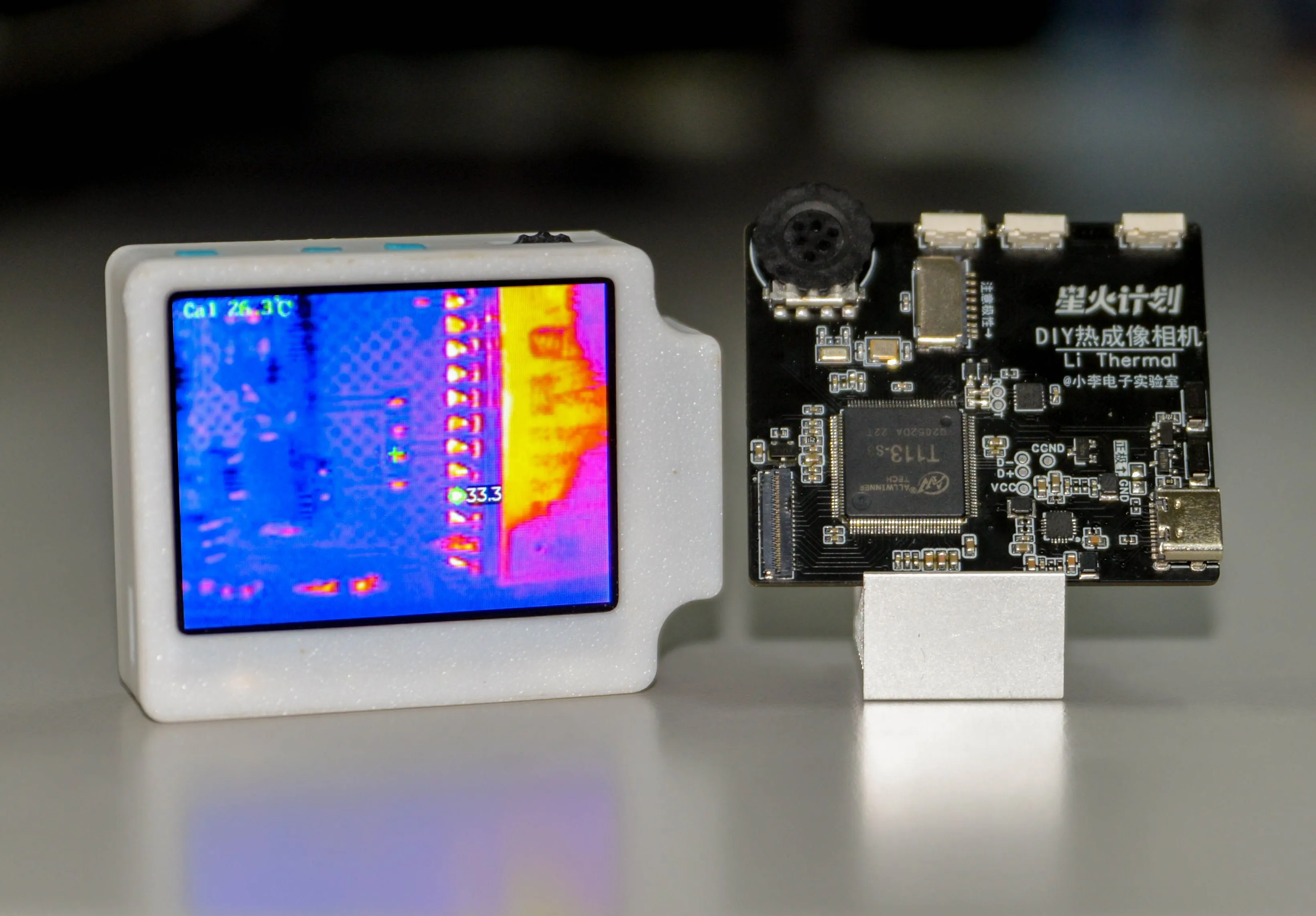
During the process of hardware debugging, we often need to check which electronic components are generating heat.
Not only will the PCB be dirty using traditional methods, some small hot spots are difficult to locate using this method.
Some of our open source thermal imaging works are based on MLX90640, which have high appearance but low resolution.
Some are based on Hikvision 4117 and have high resolution , but the APP is not smooth enough to use.
Based on this, I wanted to combine the advantages of both and designed this thermal imaging camera
Not only does it have the resolution of Hikvision 4117 , it is also smooth enough . Almost all animations can reach a 90Hz refresh rate and support interrupted animations .
Moreover, all software and hardware are open source!
Station B demo video : https://www.bilibili.com/video/BV1e4xeeCEGL
Github open source link:https://github.com/diylxy/LiThermal
[Related pictures added after the National Day]
Its functions are:
Take a photo (you can get full-screen temperature data while taking a photo).
Video.
View photo album.
View the maximum, minimum and center values of temperature.
Temperature chart.
Modify color palette.
Redirect the background management page, which can be accessed through a computer.
System Configuration
SoC: Allwinner T113-S3
Frequency: 1 GHz * 2 cores
Memory: 128MB on-chip
Screen: 2.4-inch TFT LCD, 320x240 @ 94.3 Hz
Thermal imaging refresh rate: 25Hz
Temperature measurement range: 0-106.4 ℃ (I haven’t tried it in subzero temperatures, but it is said that it can measure -20 ℃)
Sensor resolution: 160*120
Operating system: Allwinner Tina Linux, based on OpenWRT
GUI: LVGL 8
Reproduction Tutorial
Note: This work involves a lot of 0402 components and pin welding with a pitch of 0.3 mm, which is slightly more difficult, so please be mentally prepared . Before welding, you need to prepare a soldering iron, hot air gun, flux, and ribbon.
[Hardware]
PCB proofing parameters: double-sided, board thickness 1.2mm
The components are the same as the BOM list. You can purchase them directly by comparing them. The relevant precautions for PCB welding are marked on the PCB silk screen layer. Please confirm the component orientation again before welding.
Screen purchase link:https://item.taobao.com/item.htm?id=577414614398
I personally feel that the screen connector from LCSC is not easy to solder. You can buy this one:https://item.taobao.com/item.htm?id=717518604324
If the steel mesh is not opened, it is recommended to weld parts other than the T113-S3 chip first to avoid abnormal output voltage of the power circuit from damaging the T113 chip. Test method: Connect one end of R5 connected to EA3036 to the VCC_PMU network, plug in the USB power supply, and measure the 3 output voltages of EA3036, which are: 1.5V, 3.3V, and 0.9V. If the voltage is wrong, please check whether the three feedback (FB) pins of EA3036 are soldered.
After the power circuit test is normal, you need to burn the program for the 51 microcontroller first, use the USB to serial port to connect the two serial port test points next to the STC8 microcontroller, and use the STC-ISP software to burn the hex firmware. When burning, it is recommended to disconnect the two 0-ohm resistors first. The relevant project files are in the attachment at the end of the document or on Github.
Then test whether the microcontroller is working normally: press and hold SW1 for 3 seconds while plugging in the USB power supply, and measure whether EA3036 has 3 power outputs. If not, you need to check whether there is any virtual soldering.
Finally weld T113-S3.
Test whether T113-S3 is working properly: insert USB into the computer, press and hold SW1 for 3 seconds. If you can hear the prompt sound of inserting the USB device and the device manager finds a USB device without driver installed, it means T113 is working properly, otherwise please check Check whether there is a weak solder or short circuit in T113. Check whether the 3-way power supply of T113 is normal.
[Software]
Relevant software information is in the attachment at the end of the article.
After all the hardware is completed, you need to use Phoenix Card to burn the firmware into the TF card. Open the Phoenix Card software, insert a TF card below 32G and unplug the irrelevant USB storage device, select the img file, select "Start Card", "Burn Card", and wait for the burning to complete.
After the burning is completed, insert the card into the TF card slot on the PCB, insert the USB into the computer and press the power button (SW1) for 3 seconds. If the screen lights up and displays the power-on logo, it means everything is normal.
If there is no display, or the display is blank, but there is a USB device flashing on the computer, please wait for 3 minutes and operate according to the situation:
1. If the computer finds the MTP device within 3 minutes, it means that your screen interface or the place where T113 is related to the screen is not welded properly.
2. If the MTP device is not found, but the phenomenon is the same as if the driver is not installed, it means that your TF card is not soldered properly or does not support the TF card.
3. If the display is blank, the screen brightness will change, the same as 1.
If everything is normal, copy the contents of "Copy the contents of this folder to the root directory of the MTP device" in the relevant information to the root directory of the MTP device generated by thermal imaging. At this point, restart the device and you should be able to see the boot animation, but it will be stuck because we haven't connected the thermal imaging module yet.
The thermal imaging module is connected to the PCB via USB, and the four lines required for USB are explained on the PCB silk screen layer . Before connecting, you need to set the Hikvision 4117 to NCM mode through the 88179 network card , and set the module's IP address through Hikvision's " Device Network Search " or " 400 Password Reset Tool " (which can be found on the Hikvision official website ) is 192.168.64.64 , and the administrator password is set to Ab123456.
[Shell assembly]
[To be added]
About Commercial Use
This work is open source under the GPL3.0 agreement and is allowed for commercial use , but the startup logo in the program must be retained, and the original author must be marked : Bilibili Xiaoli Electronics Laboratory.
Designed by 小李电子实验室 (from OSHWHub)
Link:https://oshwhub.com/lxu0423/lithermal-thermal-imaging-camera
Design Drawing
 Empty
Empty
Comment