 Completed
LeTian-robot2 (wheel Legged robot)
PRO LeTian-robot2 (wheel Legged robot)
License
:GPL 3.0
Description

1. Project Source
LeTian-robot2 (wheel-legged robot) , the project is inspired by the Ascento robot. The original intention of the design is to learn the control algorithm and realize the final jumping function through the production of wheel-legged robots. Due to the huge theoretical knowledge of the entire system, the theoretical design, modeling and simulation, and physical simulation of the limited-capacity jumping function have not yet been implemented. It is expected to be implemented before June next year. The currently implemented functions include automatic shut-off and self-balancing, height adjustment, and wireless control . Since ESP32S3 supports offline speech recognition, offline speech recognition will be added to this project in the next step. Offline speech development only supports the ESP-IDF platform.
2. Project Attributes
The structural design reference is completely open source with the Ascento robot, PCB, schematic, 3D model, BOM, etc.
3. Hardware Part
The circuit part of this design was all completed by JLC EDA Professional Edition, and CAD and Solidworks were used for drawing.
(1) Supported chip: ESP32-S3-WROOM-1-N8.
(2) Pinout: two servo interfaces, two brushless motor interfaces, two IIC interfaces, and four SPI interfaces.
(3) The length and width of the onboard MPU6050 are designed to be 48*48mm, which makes it compact in size.
(4) Use DRV8313 as the driver chip with a peak current of 2.5A , and the drive motor can only use a pan/tilt motor (phase resistance is about 10 ohms)
(5) Two-way servo interface, using XH2.54 3P interface.
(6) ESP32 integrates a one-click download circuit , uses the CH340K serial port chip, and uses the typec interface to communicate with the computer and download programs.
(7) ESP32 reserves IO 0 button and RST reset button.
(8) Two FPC 0.5mm 8P LCD interfaces are reserved, which can control two 1.28-inch circular screens.
(9) LM2596 is used as a 5V voltage stabilizing component to power the steering gear.
(10) The power input can use XT60 input, and the power supply uses 3S lithium battery.
4. Hardware Selection

4010 motor

Wheels (interference fit directly with the motor)

Steering gear
5. PCB Version
(all PCBs are drawn using JLC EDA Professional Edition)
V2.0

Front

Reverse side


The V2.0 PCB version adopts a 3-layer connection method. The main control is separated from the motor drive main control. The motor drive is driven by L6234D, and the motor power supply uses dual-channel boost chips for separate power supply. The cost is high and it should not be used.
V3.0 (final version) (Unfortunately due to the epidemic, the SMT V3.0 board has been lying in Cainiao Station and cannot be obtained in a short time. It is temporarily driven by V2.0 main control and power layer + 4010 motor alone. Control, due to a problem with the left wheel motor, the final control effect is not good, the latest 3.0 version program will be updated after the epidemic situation improves)


Main control layer (note: please use wires to connect the back VCC)


Power layer (leads out the servo and motor interface)


Encoder (AS5600 chip)
4010 MOTOR single-channel simpleFOC control panel ( reserved for serial port 0 communication )


6. Software Implementation
Due to the epidemic, the PCB of version V3.0 cannot be obtained. The current hardware version uses the main control + power layer + 4010 motor driver of version V2.0. Therefore, the motor driver and main control code of this version are separated and calculated in different main controllers. accomplish. All V3.0 version motor driver integration is completed by an ESP32S3. When the epidemic situation improves in the future, the code debugging of version 3.0 will be carried out.
Code development platform: VScode platform.
Hardware structure.

The motor drive is implemented using the SimpleFOC algorithm, and the motor runs in torque mode.

The main control and the motor driver use serial communication to set the target value and read the speed and angle values.


The motor is initialized for the first time motor.initFOC(); delete the parameters in the function, wait for the serial port to output the motor rotation and deviation angle after the motor is powered on, and fill in the motor self-test next time it is powered on.

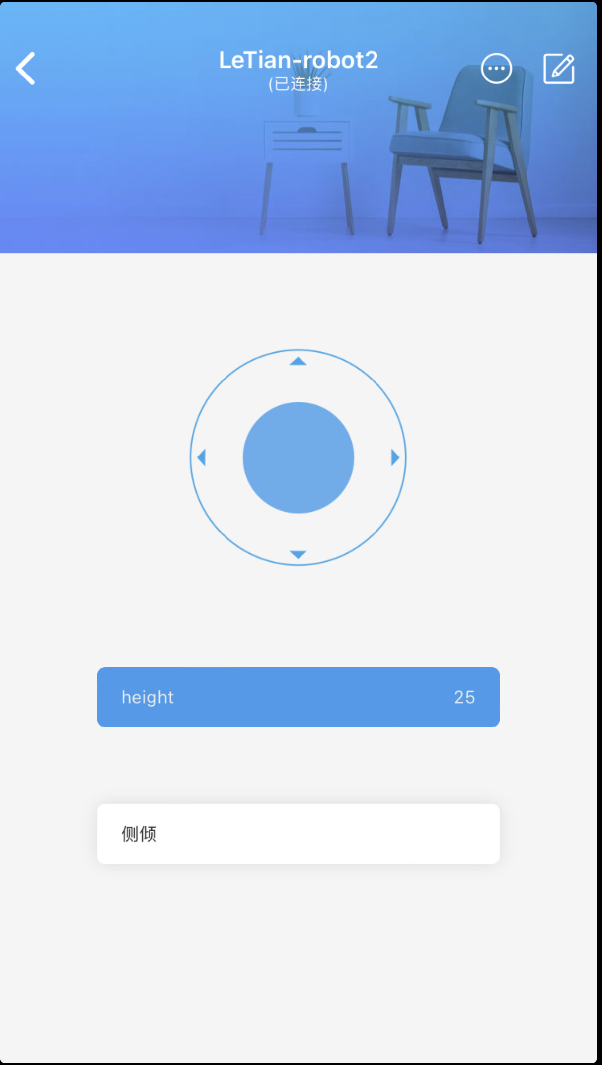
The main control runs ESP32 RTOS and creates two tasks, serial port control of the motor and reading of motor angle information. At the same time, the Blinker APP can be used to control using Bluetooth.

Read wheel speed information, MPU6050 information, and perform PID calculations.

Give the motor torque value through serial communication, run blinker for Bluetooth control, and update at the same time; the steering gear angles on both sides.

PID parameter adjustment.

Blinker APP 
Due to time and epidemic reasons, we will continue to optimize the mechanical structure and algorithm in the future, improve stability and anti-interference, and add more functions. Currently, self-balancing, height control, and tilt angle control have been achieved. The next step will be to achieve balance on complex terrain. As well as developing code writing and debugging in the ESPIDF environment.
Reference link: https://www.bilibili.com/video/BV15W4y1H7Kb/?spm_id_from=333.999.0.0&vd_source=fa8c62cf1b1a4771b713149461b59df7
https://www.youtube.com/watch?v=f9GJqqUpL2w
All PCBs, schematics, 3D models, and BOM lists are open sourced. Please like, collect and repost them, and you can also discuss them in the comment area.
Designed by LeTian (from OSHWHub)
Design Drawing
 The preview image was not generated, please save it again in the editor.
 Empty
Empty


Comment