Editor Version ×
recommended

Pro Edition

free

Brand new interactions and interfaces

Smooth support for design sizes of over 3W

devices or 10W pads

More rigorous design constraints, more

standardized processes

For enterprises, more professional users

Std Edition

Easy to use and quick to get started

The process supports design scales of 300

devices or 1000 pads

Supports simple circuit simulation

For students, teachers, creators

Completed

PRO MakerLab [lckfb] Liangshan RoboMaster expansion board

[lckfb] Liangshan RoboMaster expansion board

Project tags

License

GPL 3.0

License: GPL 3.0

Mode:

Mode

Editors' pick

Editors' pick

  • 49
  • 0
  • 0
Update time: 2024-12-18 10:07:26
Creation time: 2024-12-17 03:40:35
Description

Description

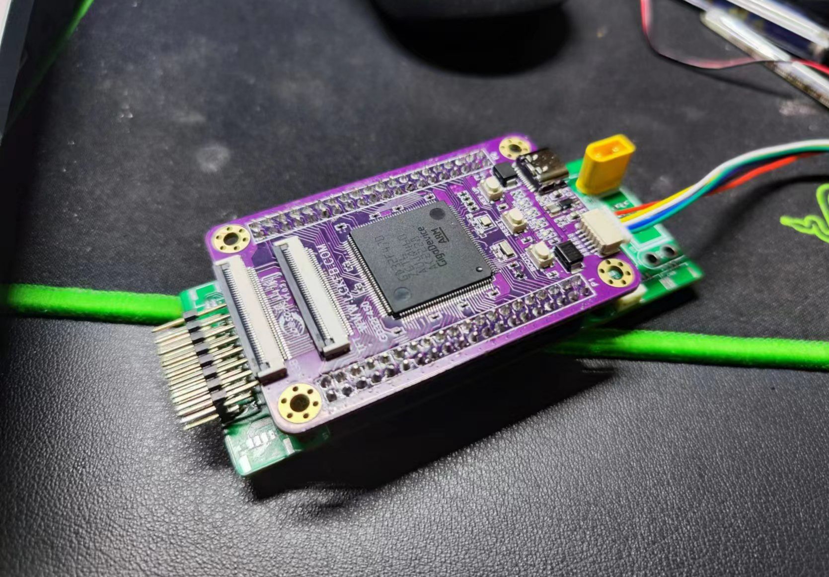
# Introduction to the work This project comes from the winter vacation training camp of Lichuang Liangshan pi development board, based on Liangshan pi to produce RoboMaster main control expansion board, and refer to the original [C-type board](https://www.robomaster.com/zh-CN/products/components/general/development-board-type-c/info) for circuit design. The expansion board expands the functions of 24V (6S battery) step-down, USART, CAN, PWM, battery voltage monitoring, etc., and can be used with the host computer to realize visual control and other functions. # Photo show ![屏幕截图 2023-02-13 144559.png](//image.lceda.cn/pullimage/hJIqfUR8yeQS2bpoWwvCmXtJYMciXuA8G5BkX9xL.png) ![微信图片_20230223002400.jpg](//image.lceda.cn/pullimage/Dj7lymiRbu0kxFFEMwOHQ8crgqMbCSIJ7DI2UYKY.jpeg) # Description of the function ## Advantages of Liangshan Pi Liangshan Pi has a rich storage configuration,Onboard8MBSpi flash、SDRAM、MicroSDCs,Dual LCD screen interfaces,It's been a few streets away from the cheap core board,The last one I used with this configuration was 300 pieces of STM32H7 a certain Pi。 The use of these advanced extensions is being investigated to write the program to an external SPI flash with control algorithms, while also storing the configuration information of the trolley. ## Hardware design I tried JLC's four-layer board for the first time, and the experience was very good. The patch is cool for a while, and the crematorium is welded. ## 24V step-down circuit The power supply part is equipped with one XT30 input and three XT30 output interfaces (24V). In order to adapt to the 6S power battery, a 24V step-down 5V1.5A circuit (MC34063ADR2G) is designed to supply power to the core board and CAN chip through the 1117_3.3 LDO. One 24V step-down 5V3A (TPS5450DDAR) is used to drive high-power equipment such as servos, ESCs, and remote control receivers. ![image.png](//image.lceda.cn/pullimage/CYUvPwwkipxlVzVf2jFFWJfUETssmwkGNaNIGIOw.png) !Note! The 1.5A step-down circuit can step down by 5V, and it is no problem to charge the mobile phone, but it will lose power when plugged in to the Liangshan Pi, which has not been ruled out for the time being. The 0R resistor is used with two output capacitors, and the whole board is temporarily powered by 5V3A. ## ADC voltage monitoring Voltage monitoring uses the PA1 pin, which is connected to the resistor after dividing. ![image.png](//image.lceda.cn/pullimage/L84BAZbkSJOquDa9C0SLKRE8qVgndxgm4HrzDZM4.png) ## USART Enable USART0 and USART1. USART1 is connected to the host computer for line identification, and the trolley is controlled to patrol the line. ## DBUS receiver The trolley can be operated remotely using the DJI DT7 &DR16 remote control receiving system. The receiver uses the D-BUS protocol to communicate with the Yangsan faction, which is essentially USART, using USART2_RX (PC11). Since the high level represents 0 and the low level represents 1 in the DBUS protocol, a MMBT3904 inverter is added to the receive circuit. et parameters: baud rate 100Kbps, 8 bits of data, even check, 1 end bit Reference:[DT7&DR16 2.4GHz](https://www.robomaster.com/zh-CN/products/components/detail/122) ![image.png](//image.lceda.cn/pullimage/Q9hFtxpWZXIBpWmrqi9Exzvmcwm14nRLyrjXF7gA.png) ## CAN bus The extended version enables CAN0 (PD0, PD1) and CAN1 (PB12, PB13) and is driven by a TJA1044GT/3Z CAN transceiver. The four wheels equipped with the trolley are communicated through the CAN bus, and the connector is GH1.25 series, which can realize the two-way transmission of control data, send control information from Liangshan Pi, and read the angle, speed, current and other information of the motor. Pay attention to the CAN_H and CAN_L as far as possible to equal the length difference distribution line; If a 120R resistor is already included on a bus, R21 and R22 can be left unsoldered. ![image.png](//image.lceda.cn/pullimage/RIdnvr0Qa1Z0LcfBrsyjpDHvOxj0xc35zz46svy5.png) ## PWM Leads out 6 sets of PWM pins for subsequent expansion of other functional ESCs. ![image.png](//image.lceda.cn/pullimage/booXshvWbyv0EGbt85GO3Z1qgTnXy28Z73pw8SCG.png) ## LED Pin PA5 is used to control the LED of WS2812, and the data output pin is reserved for external expansion of the LED strip. ![image.png](//image.lceda.cn/pullimage/3I2MLfH6LqtFcIyVhXYgScJh4hiXi1Bzl5y4pZVb.png) ## Other features elicit out I2C ![image.png](//image.lceda.cn/pullimage/YmAO1qGkWr5XHM6E4OzNDenZ6Nl2D9QQ84z7V8mt.png) # Program code The program is developed using MDK-ARM, and the driver is ported with reference to the open-source C-type board routine. The CMSIS-RTOS2 real-time operating system is enabled, and some of the basic code will be open-sourced in the future (after improvement). # Summary - In my freshman year, I came into contact with the LC training camp, and I went step by step, studied (baipiao) for three years, and gained a lot. - This work does not implement some of the functions shown in the example, which is a bit insufficient, because these functions are not used to run on a microcontroller in my project. There was no tutorial on the required CAN bus in the learning materials, so I spent a lot of time looking through the official GD materials and porting the drivers on my own, and finally achieved the desired goal. (If the Liangshan Pi wants to add CAN bus teaching materials, you can discuss it together) - The actual use experience of the Liangshan Pi is also very good, and with the self-designed expansion board, it is expected to be replaced by localization (bad laugh)
Design Drawing

Design Drawing

schematic diagram
1 /
PCB
1 /
The preview image was not generated, please save it again in the editor.
Empty
Project Attachments

Project Attachments

Project Members

Project Members

Target complaint
Related Projects
Change a batch
Loading...

Comment

Add to album ×

Loading...

reminder ×

Do you need to add this project to the album?

服务时间

周一至周五 9:00~18:00
  • 0755 - 2382 4495
  • 153 6159 2675

服务时间

周一至周五 9:00~18:00
  • 立创EDA微信号

    easyeda

  • QQ交流群

    664186054

  • 立创EDA公众号

    lceda-cn