

 Completed
Intelligent High-Power Electronic Load
PRO Intelligent High-Power Electronic Load
License
:GPL 3.0
Description
Intelligent high-power electronic load based on AT32F435, supporting external temperature sensors, program control, scripts, offline logs, CAN expansion, cool UI, etc.

1. Preface:
Electronic load is already a well-known thing, so why do we still need to do it? Yes, what others do is too rubbish. I mean, everyone who is doing it is rubbish. So here comes the high-power intelligent electronic load. Firstly, it has sufficient power, stable 300 watts, CPU-level 3 fans and 6 copper tube professional heat sinks. Secondly, it is intelligent enough to support CAN bus interconnection, script programming, external NTC, PTC, serial port screen and other data collection and display. Later, consider 4 tubes, 600W and wireless functions.
2. Introduction to the plan
In order to be intelligent enough, cheap microcontrollers must be abandoned first, and a more powerful AT32F435 is selected to run LVGL smoothly, provide a cool GUI interaction experience, and have enough flash memory and memory to run the script environment
2.1 AT32 minimum system
Designed high-speed external crystal oscillators and low-speed external crystal oscillators, providing accurate system clock and timing functions, supporting BOOT0 independent settings, battery interfaces, etc

2.2 1.47 Color screen interface
Onboard 1.47-inch color screen, SPI interface, resolution 320 * 172, supports independent backlight adjustment, and can also connect larger screens and touch functions through the board interface.

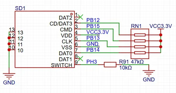
2.3 Memory card interface
Used for storing offline logs, selecting scripts, etc
2.4 Buzzer interface

2.5 CAN bus interface

2.6 SPI FLASH

2.7 Lithium battery charging port

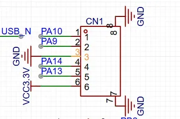
2.8 USB HOST interface

2.9 Debug interface
2.10 Expansion interface

2.11 Voltage acquisition circuit
The voltage acquisition circuit is divided into four groups, which respectively collect the system power supply (12~ 36V, which supplies power to the whole machine, including the cooling fan, with high power consumption), the input power supply (that is, the power supply input is used as the load), the system 5VDCDC voltage (USB power supply unidirectional input), and the lithium battery voltage.

2.12 System DCDC

2.13 Fan interface

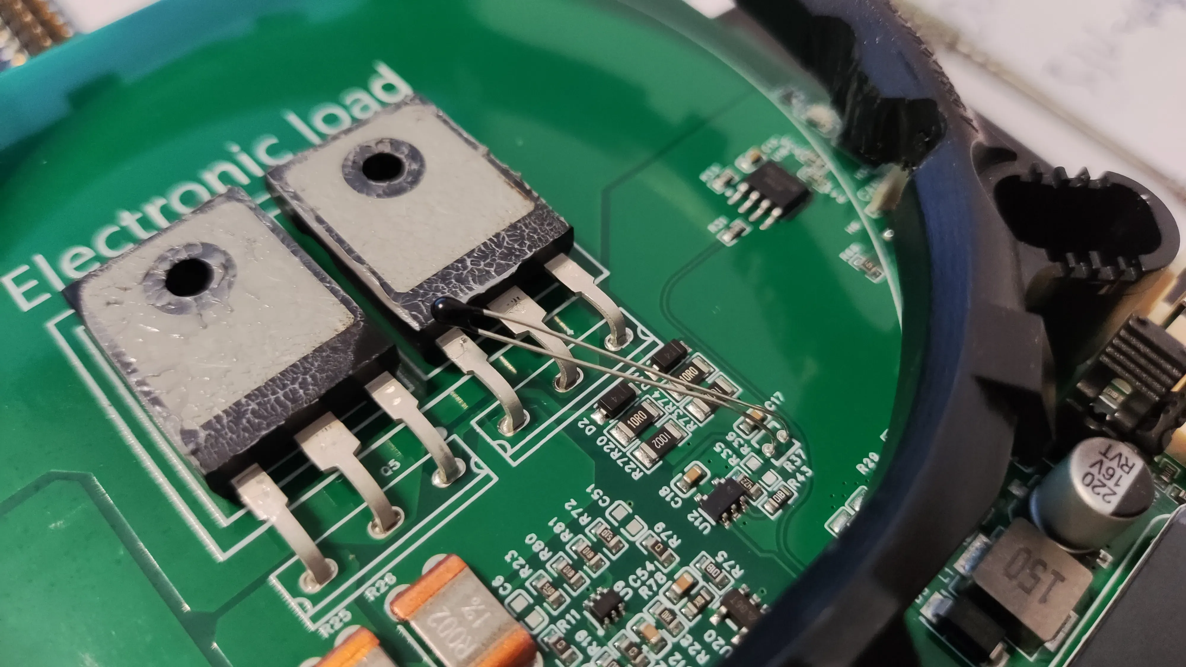
2.14 MOS Load Circuit

3. Software development
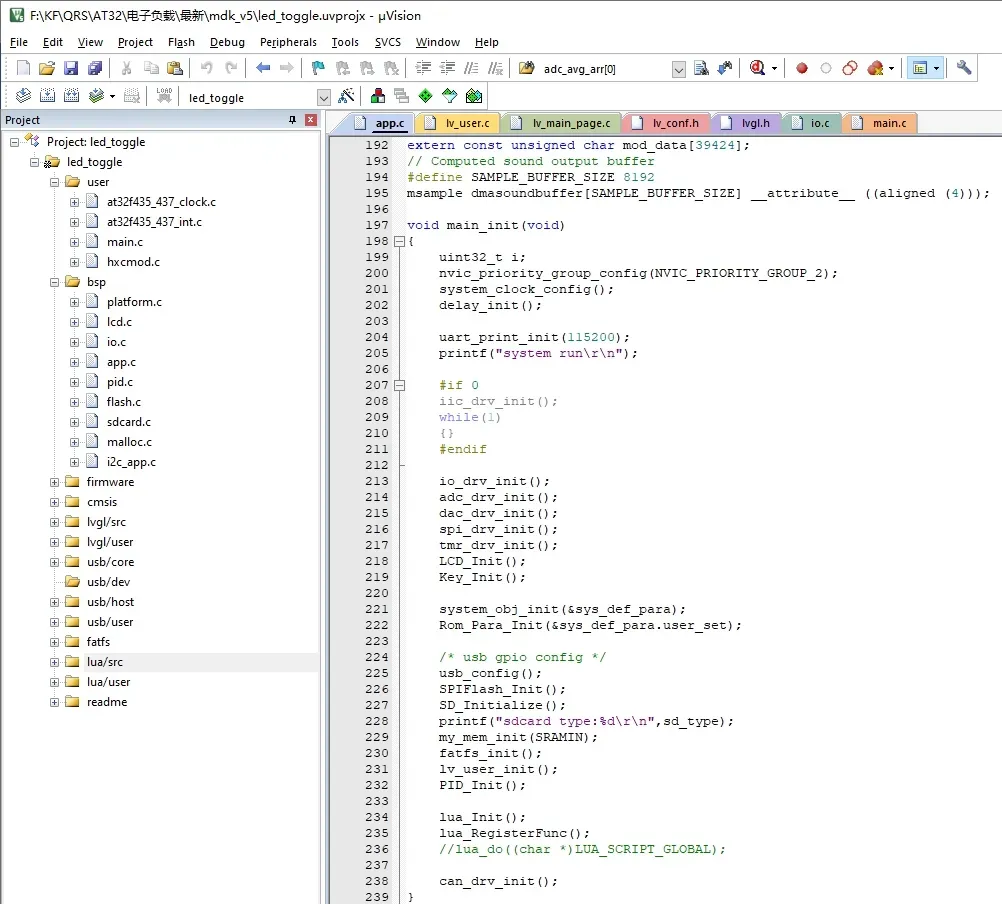
File grouping user: main function
File grouping bsp: hardware driver
File grouping firmware: MCU firmware library
File grouping lvgl: lvgl library
File grouping USB: USB library
File grouping fatfs: file system library
File grouping lua: script library
Introduction to bsp function: Platform is the MCU board-level bottom driver, such as system tick timer, system time base, debug serial port, etc. MCU platform-related initialization, lcd is screen initialization, IO is hardware interface initialization, including IO, SPI, IIC, timer, ADC, DAC, CAN, etc. Initialization, app is the application layer, pid has been deprecated, flash is the MCUFLASH operation part, sdcard is the memory card driver, using SPI interface, malloc is memory allocation, used to initialize the memory environment for lua script, i2c_app is the hardware IIC test function, deprecated.
The program uses software timers to manage foreground processes. The main loop is responsible for USB host polling, and the USB mouse is used to control the UI. The 50ms cycle task is used to switch UI interfaces and control DAC load currents. In the future, UI interaction and Lua interfaces will continue to be optimized. Stay tuned!!!
The program attachment cannot be placed, put it in gitee: https://gitee.com/lovelessing/electronic-load.git
4. Replication steps
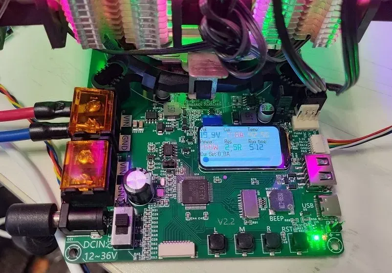
If nothing unexpected happens, the board in hand should look like this, and it is basically welded
The back of the solder mask window current enhancement can be repaired if conditions permit (if the current exceeds 50A).
Then install the radiator base with M4 screws and download the program

The current enhancement of the solder mask window on the back can be repaired if conditions permit (if the current exceeds 50A).

Then install the radiator base with M4 screws, and then download the program.


Designed by lovelessing (from OSHWHub)
Link:https://oshwhub.com/lovelessing/intelligent-high-power-electroni
Design Drawing
 Empty
Empty
Comment