

 Completed
Household socket intelligent monitoring system
PRO Household socket intelligent monitoring system
License
:GPL 3.0
Description
Household socket intelligent monitoring system completed
Design and revision based on intelligent electricity safety monitoring system
https://oshwhub.com/qusenberg/yong-dian-she-bei-zhi-neng-jian-
————————————————————————————————————————————————————————————
Hardware usage introduction:
1. When using TYPE-C power supply, it can only be used to test functions. The left switch only controls the 5V power supply of TYPE-C. The 220V (AC) to 5V (DC) power supply does not support power-off by the left switch.
2. When using the national standard power cord (three-hole power cord), there is no need to connect to TYPE-C for power supply.
3. After connecting the national standard power cord (three-hole power cord), wait 2 seconds for the system to power on. There will be a 2-3 second self-test time after the system is powered on. At this time, three indicator lights and a buzzer will work. Complete Enable working mode after self-test.
4. Introduction to onboard LED functions:
1). The YLED (yellow LED) indicator light flashes to indicate that the relay is disconnected. When the relay is closed, the yellow LED is always on.
2). The RLED (red LED) indicator light is always on, which means that the maximum power exceeds the limit value. (This program is designed for up to 1200W)
3). The BLED (blue LED) indicator light is always on, which means the 220V AC power is connected.
5. After powering on, the display will display voltage, current and other numerical values.
6. There are 3V, 5V and relay indicators on the board. If the relay indicator light is always on, it means the relay is closed, otherwise the relay is open.
7. Functions of the four buttons on the right side of the device:
1). The △ button has no function set yet. The corresponding stm pin is PA6.
2). Press and hold the power-on button to close the relay. The corresponding stm pin is PA5.
3). Press and hold the power-off button to disconnect the relay. The corresponding stm pin is PA4.
4). The reverse △ button has no function set. The corresponding stm pin is PA3.
Introduction to wireless serial communication:
1. This device provides two WiFi transmission interfaces:
1). The esp-01s on the left only supports wireless serial port data transmission and does not support the online debugging function of keil software.
2). The interface on the right side is externally connected to the multi-function downloader provided by @ steering gear workshop boss. After being connected, the device supports keil's Download.
Project address: https://oshwhub.com/q837877663/duo-gong-neng-wu-xian-xia-zai-qi
2. Instructions for using the keil online download function:
1).

2).

3).

4). After setting up according to the picture, you can program the program. Please click the Bulid button before burning.

Introduction to using the host computer:
1. Open the remote intelligent control software and click the communication setting button in the upper right corner of the stand-alone machine.
2. Select the corresponding serial port number - click to open the serial port - check Show data and Show original code
3. Return
4. Select channel 1 in the channel control - select the channel in the three windows - display parameters and select voltage and current as needed. Power parameters.
5. After the connection between the device and the host computer is completed, click to turn on the device - check the smart control in the upper right corner - the device is connected to the electrical equipment - then you can click the record button (record the power consumption data of the electrical equipment at this time, and the time will not change within one minute. You must control it yourself) - After recording, click to turn on monitoring to complete the intelligent monitoring settings. If the power of the electrical equipment is greater or lower than the recorded data, the host computer software will have a text prompt. When the host computer is set to exceed 30% of the recorded data, the power will be automatically cut off (open the relay).
Compiled on 2023-3-10
Some omissions need to be added.
————————————————————————————————————————————————————————————
Hardware iteration update says:
V5.0 version Demo-2023.1.7
1) Added button control relay.
2) Added W2812B RGB indicator light.
3) Added EC11 knob encoder.
4) Added a multi-function wireless downloader socket (project address: https://oshwhub.com/q837877663/duo-gong-neng-wu-xian-xia-zai-qi)
V5.1 version Demo-2023.1.14
1) Fix relay pin error.
2) Newly added Pinzi power socket.
3) Modification of the direction of the wireless serial port female socket.
4) Remove WS2812RGB lighting.
5) Added buzzer.
6) 3D shell opening adjustment.
V5.1.1 version Demo-2023.2.6
1) Fix the packaging error of Pinzi AC socket.
2) 3D shell hole position adjustment.
3) Update of the positions of the four positioning holes of OLED.
V5.1.2 official version-2023.2.25
1) Added CH340c downloader.
2) Detail optimization.
V5.2 official version-2023.3.8
1) Remove the EC11 knob.
2) Buzzer package update.
3) 3D shell fine adjustment.
V5.3demo version-2023.3.27 (not released, under verification)
1) TA-1005M AC current transformer (maximum support 5A ) is upgraded to xxxx, maximum support 15A.
————————————————————————————————————————————————————————————
Software update instructions:
1. The code is updated to 2023-3-9 to fix the problem of the buzzer not working.
2. The code is updated to 2023-3-16, and the LED indicator light judgment logic problem is fixed.
————————————————————————————————————————————————————————————
3D function introduction

————————————————————————————————————————————————————————————
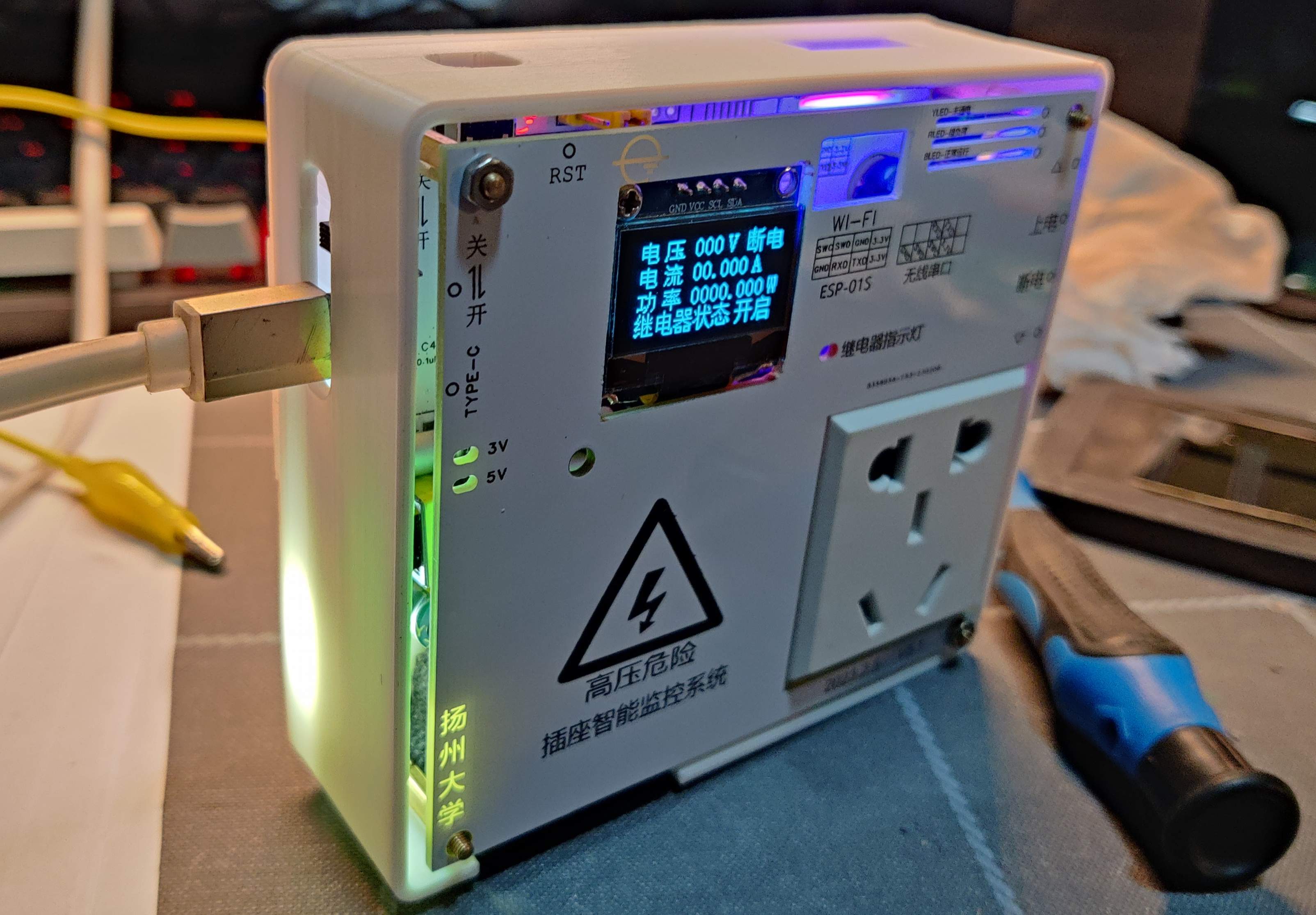
Actual picture:
Functional testing is completed and defects have been fixed.


————————————————————————————————————————————————————————————
Notice:
If you have any questions, please go to the correct channel to provide feedback, or leave a comment.
Since the project involves the use of mains power, we are not responsible for any electric shock accidents during debugging and use. Once you adopt this open source project, you will accept the risks of its existence.
Designed by Qusenberg (from OSHWHub)
Link:https://oshwhub.com/qusenberg/jia-yong-cha-zuo-zhi-neng-jian-kong-xi-tong-bi-she
Design Drawing
 Empty
Empty
Comment