

 Completed
HDMI 5 in 1 out switcher dual AG7111+ESP32
PRO HDMI 5 in 1 out switcher dual AG7111+ESP32
License
:GPL 3.0
Description
0.Preface
At present, AG7111 is very expensive (it cost 10 yuan each at the time, but now it has increased to 30 yuan) and may not be available yet, so there is a domestic alternative, ms9601:
1 cut 3 reference: https://oshwhub.com/aknice/ms9601
1 cut 5 reference: https://oshwhub.com/aknice/yin-shi-pi
Lower cost, same functionality.
It's not that AG7111 is unaffordable, but ms9601 is more cost-effective!.
1. Introduction
Use two AG7111 + ESP32 to make an HDMI 5-in and 1-out I switch, suitable for a variety of purposes.
I have also made an HDMI 3-in and 1-out I switch before. The same switch solution, but without MCU control, is more economical and affordable. Open source connection:
https://oshwhub.com/Aknice/1dfda80b41104751846aecc99dd9e055
What I did this time required MCU control, so I fell in love with the DAC function of ESP32.


It's time for the classic price comparison again.

Ma Yun.com 200 + a 5-cut 1 switch. For me, including the ESP32 and two switching chips plus peripherals, it's only 50.
2.Principle
In 3 Cut 1, we actually talked about a little bit of the principle, but not much. It was mainly about switching control and how to use MCU to control it.

It has something to do with RXSEL here. The 3-to-1 RXSEL1 here is NC, that is, RXSEL1 is floating, and floating is controlled by buttons.
Now two AG7111 are used here, so there are RXSEL1 and RXSEL2, both of which are connected to 2K pull-down.
This RXSEL is voltage controlled. According to the input voltage value, the output AG7111 can choose which HDMI port to output. Then we can use MCU to control their voltage.

This RXSEL is directly connected to the D25 and D26 ports of the ESP32.

Here is a diagram of the IO ports. You can see that D25 and D26 are exactly two DAC ports, so they can be used here.
Because there is no specific voltage specified in the specification sheet here (in fact, the specification sheet for the purpose of this port is not even written, I just figured it out by myself)
Here I tried out the corresponding relationship between ports and voltages through repeated trials:
| Port | Voltage(V) |
| HDMI1 | 0~0.2V |
| HDMI2 | 0.8~1.2V |
| HDMI3 | 1.8~2.2V |
The above table shows the corresponding relationship between HDMI switching port and voltage.
If the voltage is not within this range, an abnormality will occur.
According to the above table, and with the drop-down 2K, we can implement control in the code.

For example, port 5, which is the rightmost port of the PCB, is actually the first port of the second chip, and the first chip will not be used, so the first chip can be selected casually, that is, as long as the second chip RXSEL2 (D26) Just choose HDMI1, so the 26 voltage is 0.
For example, port 2, which is the second port from left to right on the PCB, is actually the second port of the first chip, and then output to the third port of the second chip, so RXSEL1 (D25) selects the middle of 2 Voltage, this value is 62. The second chip RXSEL2 (D26) selects the third port and is connected to the output of the first chip, so select 3. The one with the largest voltage value is 160.
In fact, if you look at the order of the chip layout, the rightmost one should be the first HDMI port, but it does not conform to our common habits, so I reversed their order.
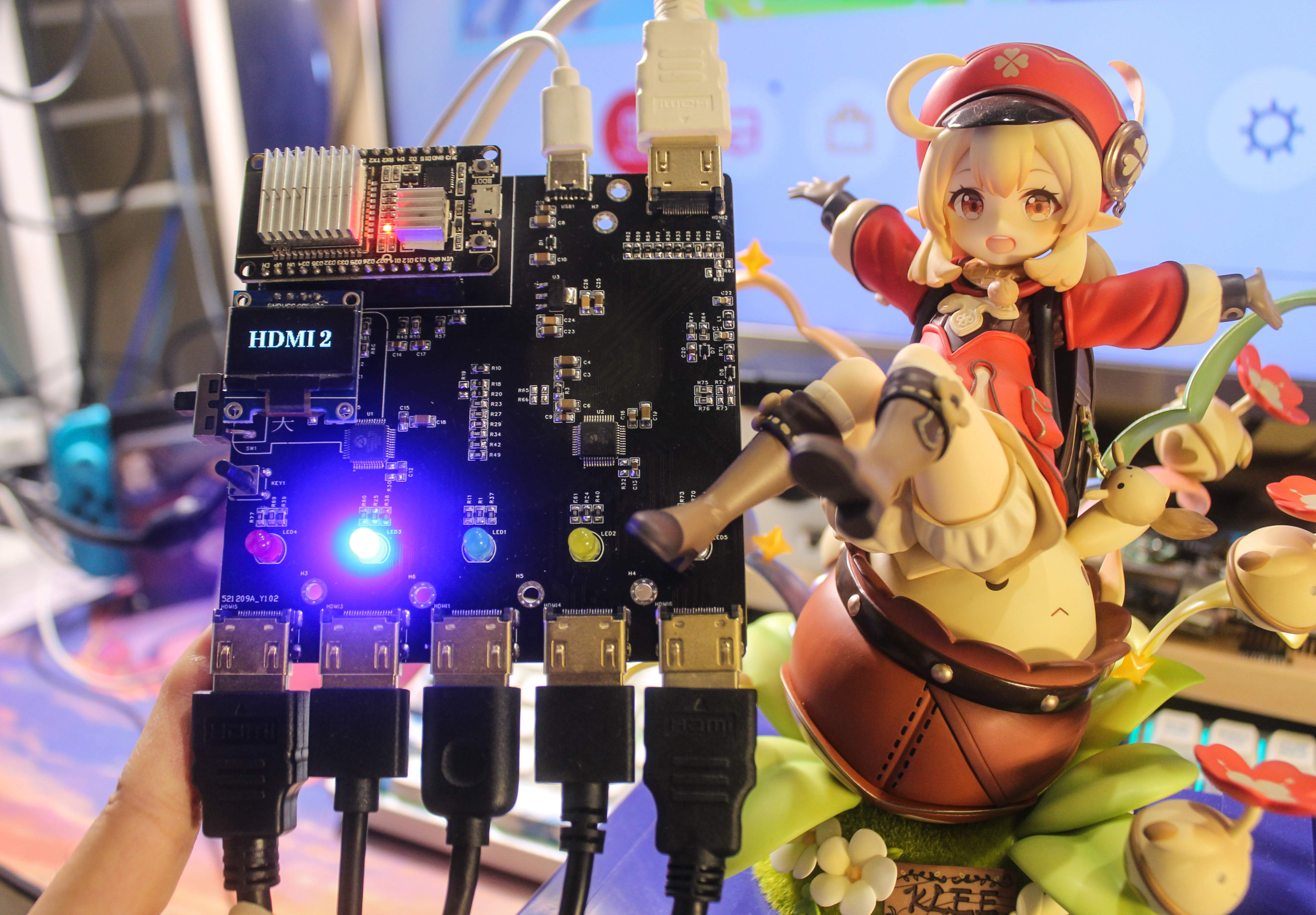
3. About the screen

You can choose one of the LED indicators and the screen. The screen does not display any other status. In addition to displaying the HDMI port, it also provides an indication that there is no HDMI output. The indicator light can be displayed, and the screen can also be displayed. We will continue to improve on this basis when we make KMV in the future.
4. Precautions for Use
It must be connected to an external TYPE-C 5V power supply, otherwise it cannot be used.
The switch on the left only controls the HDMI switch, the ESP32 and screen are not controlled.
Improve:
- Digging out the ground copper around the equal length line
- Replace LOD with low pressure difference
- Also replace the diode with a low voltage difference one.
- Video signal string beads
- HDo 100 ohm impedance matching on the HDMI signal cable (jlc can do it, but it costs extra, the prostitutes do it at will, and they don’t do certification anyway)
In addition, you can add unlimited chips with 7 inputs and 1 output, and the solution of 9 inputs and 1 output is no problem.
5.Acrylic Panel
Requires 25mm M3 copper posts*3
5mm M3 copper pillar*4

laminated structure
In addition, the button needs to be printed with a button, otherwise it will be too long, or you can use a side-mounted one instead.

6. Demo Video
Designed by __Aknice (from OSHWHub)
Link:https://oshwhub.com/Aknice/83d25e9c5f9240499dfcd01eeaa45b82
Design Drawing
 Empty
Empty
Comment