

 Completed
[ESP32-S3]1.69 inch touch screen mini controller ~
PRO [ESP32-S3]1.69 inch touch screen mini controller ~
License
:Public Domain
Description

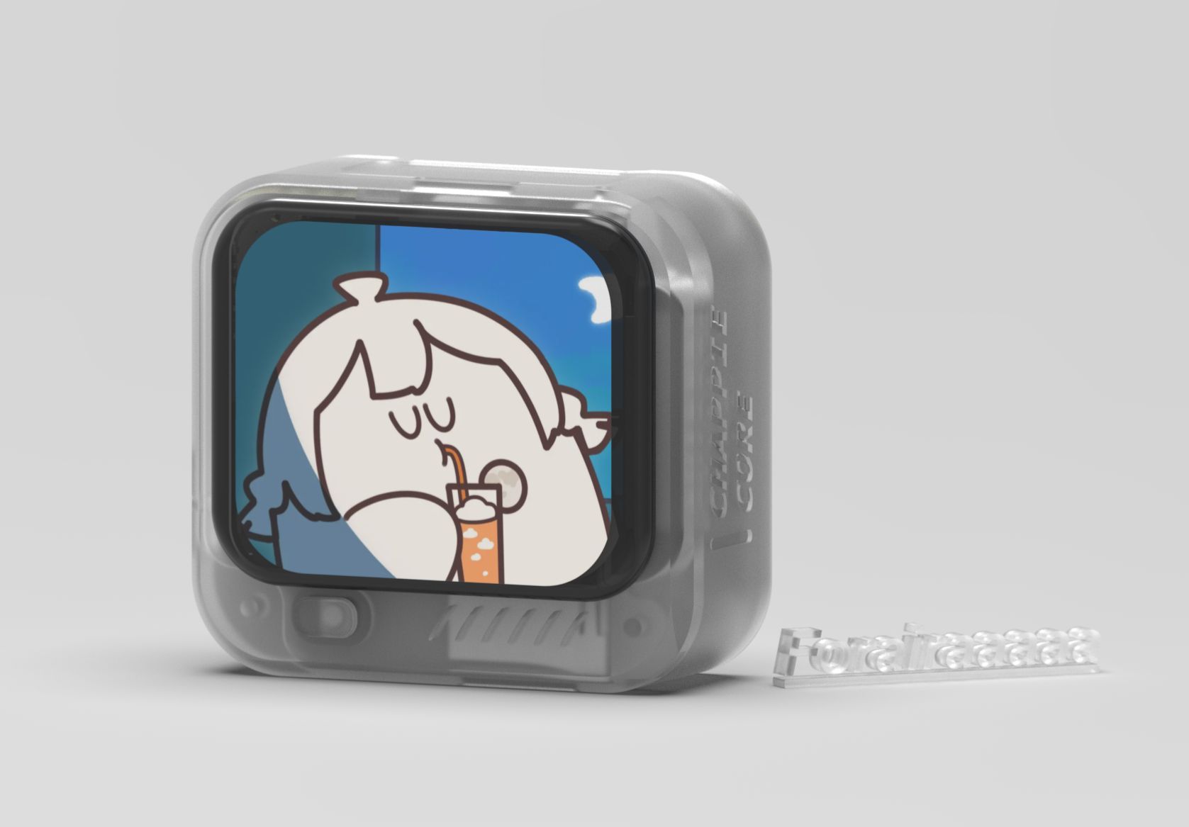
Based on ESP32-S3, it has an onboard 1.69-inch LCD assembly interface, buzzer, SD card slot, AXP173 power management, and double-row female leads to most pins for baseboard expansion functions.
PCB projects, gerber, shells, etc. are all open source~
Github link:https://github.com/Forairaaaaa/Chappie-Core
Video introduction: https://www.bilibili.com/video/BV1dS4y1p7am\


PCB layout:


Due to the use of the ESP32-S3 WROOM module and the previously designed AXP173 small power management module, the overall circuit composition is not complicated. The overall schematic diagram is as follows~

The following structural diagram integrates some commonly used peripheral circuits, and leads out the remaining pins through female headers for connecting to the baseboard to expand functions.
The Type-C interface is directly connected to the USB pin of the ESP32, and the program can be programmed and log printed through the virtual serial port. The default uart0 pin is also led out through the 2.54 pin header, but there is no opening in the shell~
The LCD uses SPI connection, and its touch screen part is connected to the I2C bus.
TF is also an SPI connection method, but it does not share a set of SPI with LCD.
The buzzer is an ordinary passive buzzer.

For more information about the power management module, please see this project: https://oshwhub.com/eedadada/tiny-pmu-axp173
It is the smallest circuit integration of the AXP173 chip, which can provide multiple controllable power supplies, battery information, power switch control, etc. ~
If you do not want to use this module, you need to arrange the relevant power circuit in the original module location to realize the function.

Different functions can be expanded through different base plates.
After connecting to the bottom plate, it forms a sandwich structure, and the battery can be placed in the middle. The warehouse provides template work for the base plate~

The printing stl file of the shell has also been packaged and organized. By default, there is no back cover, but the bottom plate template is used as the back shell. Several small buttons need to be printed together, otherwise they will be too small. The files have already been integrated in the warehouse.
It should be noted that the shell is designed based on a board thickness of 1.0mm. There may be misalignment with different board thicknesses.

There is also an expansion baseplate with two MPU6050 360° servos thrown in the warehouse, which provides 6v power to the servos through DCDC boost.
The shell Gerber is complete~, and the Src contains a real-time acceleration reading routine written by lvgl.

Connect it to the base plate and it becomes a handheld car~

Program part:
The routine is a PIO project, which takes a certain amount of time to load after opening. In addition, you need to make some file replacements after downloading the lvgl library. The README in the library has detailed instructions.
The library contains the basic bsp library based on Arduino , and has completed the transplantation of touch screen driver and lvgl, as well as the initialization of sd card, etc.

You can test the lvgl demo program by simply quoting it.

In addition, IcingTomato giant uploaded an optimized wifi image transmission routine.

~~~~~~
Designed by Forairaaaaa (from OSHWHub)
Design Drawing
Intellectual Property Statement & Reproduction Instructions
This is an open-source hardware project. All intellectual property rights belong to the creator. The project is shared on the platform for learning, communication, and research only; any commercial use is prohibited. If your intellectual property rights are infringed on EasyEDA, please notify us by submitting relevant materials in accordance with the Rules for Complaints and Appeals of IPR Infringement.
Users must independently verify the circuit design and suitability when replicating this project. All risks and consequences are borne by the user, and the platform assumes no liability.
 Empty
Empty
Comment