

 Completed
ESP32 CNC Electronic Loading Instrument
PRO ESP32 CNC Electronic Loading Instrument
License
:CC BY-SA 4.0
Description
Project Description
ESP32 multi-function CNC electronic load meter is a portable DC CNC electronic load meter and power measuring instrument powered by lithium battery, with a variety of interfaces, supporting the measurement and display of CNC CC constant current, CV constant voltage, CR constant resistance, CP constant power discharge and real-time current, voltage, power, temperature and other parameters.
Feature Introduction
1. USB TYPE-C interface supports program downloading and power supply to devices.
2. Input port: TYPE-C + XT60 + 2P fence terminal block + 2P pin header.
3. Output port: TYPE-C + TYPE-A + XT60 + 2P fence terminal block + 2P pin header.
4. ST7789V 1.54-inch 240*240 pixel color LCD display displays various parameters and the display direction and brightness are adjustable.
5. One toggle switch controls the battery to power the device and 4 micro switches for mode switching and parameter setting.
6. Input voltage: 0~50V Input current: 0~20.2A Maximum thermal design power in electronic load mode: 200W.
7. Real-time power tube NTC temperature measurement protection and display and buzzer prompt.
8. Lithium battery and USB dual power supply. When plugged into USB, the power supply will automatically switch to USB power and charge the lithium battery.
9. It has reverse connection, over-voltage, over-current, over-temperature and over-power protection, threshold setting and parameter saving when power off.
Open Source Agreement
This project is licensed under the "CC BY-SA 4.0" license. Please do not use it for commercial purposes. Please attach a link to the original source and this statement when reprinting.
Project Properties
1. This project has been published for the first time and has not won any awards in other competitions. It is an original CC BY-SA 4.0 open source project by Negentropic Light.
2. Gitee warehouse connection: https://gitee.com/arduino2021/ESP32-E-Load.git
3. The light of negative entropy 2023-8-29.
Project Progress
1. In June 2023, complete the schematic PCB design proofing verification function of ESP32 multi-function CNC electronic load meter 1.0, discover BUGs, and start writing software.
2. In July 2023, the schematic PCB of the ESP32 multi-function CNC electronic load meter 1.1 will be completed, the proofing verification function will be improved, most BUGs will be resolved, and the software will be written.
3. In August 2023, the schematic PCB of the ESP32 multi-function CNC electronic load meter 1.2 will be completed to optimize the proofing verification function, solve some small BUGs and improve the software.
4. The project went through a total of 3 versions, spent more than 600 yuan on PCB prototyping and purchasing components, and took more than 3 months of time and effort to finally take shape.
Design Principles
1. This project uses ESP32-S3FN8 as the main control to collect voltage and current parameters in real time through INA226 to control the output reference voltage of the MCP4726 DAC chip.
2. The constant current op amp controls the VGS voltage of the power NMOS by comparing the DAC reference voltage with the current sampling overcurrent resistor voltage divider to control the flowing current to achieve constant current control.
3. CC constant current control realizes constant current control by controlling the MCP4726 DAC output reference voltage to control the current flowing through the power NMOS.
4. According to U*I=W, CP constant power control can be converted into constant current control through software calculation of W/U = I to achieve constant power control.
5. According to U/R =I, CR constant resistance control can calculate the current value through software to become constant current control and realize constant resistance control.
6. CV constant voltage control Because the general power supply is not an ideal voltage source and has internal resistance and cannot output infinite current, it can achieve constant voltage control by consuming current to lower the voltage.
7. Small current measurement uses ESP32 S3 ADC to collect the current divided by the precision op amp amplified current flowing through the 10R sampling resistor to obtain uA-level current information.
Function Mode Button
1. Electronic load mode: Long press the K4 key to switch the CC CV CR CP mode and set the limited running time and cut-off voltage. Short press to control the parameter bit selection. Short press K1 K2 to set the parameters of the corresponding mode. Short press K3 to control whether to run.
2. Power measurement mode: automatically measure the input to output voltage, current and power and draw a curve. Short press K3 to control the output NMOS switch. Press and hold the K4 key to clear the mode running time and accumulated power to 0 and restart the accumulation.
3. Calibration setting mode: Long press the K4 key to change to different calibration setting parameters. Short press the K4 key to select parameter bits. Short press K1 and K2 to subtract or add parameters. Short press the K3 key to set parameters or save the default settings to restore. default value
4. Key function: Long press the K1 key to switch to different modes. Short press the K1 K2 key to subtract or add parameters. K3 key controls OFF/ON. Confirm the K4 key. Short press to control the parameter bit selection and long press to switch to different secondary modes and parameters.
5. The fast charging protocol detection circuit of the TYPE-C interface is reserved but there is no time to develop the corresponding functional program, so the components related to this function can not be soldered.
Electronic Load Mode
1. Press and hold the K4 key to switch the CC CV CR CP mode and set the limited running time and cut-off voltage.
2. Short press the K4 key to control the bit selection of the corresponding parameter. Short press K1 K2 to set the parameters of the corresponding mode. Short press K3 to control the mode switch.
3. Voltage input range: 0V~50V Current input range: 0~20.2A Maximum thermal design power in electronic load mode: 200W.
4. CC constant current mode: Current setting range: 0~20.2A Current adjustment step: 10A/0.001A Current control accuracy: 0.01A.
5. CV constant voltage mode: Voltage setting range: 1~ 50V Voltage adjustment step: 10V/0.001V Voltage control accuracy: 0.1V.
6. CR constant resistance mode: resistance setting range: 0.1~999.9R resistance adjustment step: 100/0.001R resistance control accuracy: 1R.
7. CP constant power mode: Power setting range: 0~200W Power adjustment step: 100/0.001W Power control accuracy: 0.1W.
8. Cut-off voltage mode: When the VIN input voltage is lower than the cut-off voltage mode, the discharge mode is turned off. Cut-off voltage range: 0~50V.
9. Time-limited discharge mode: Discharge mode is turned off when the limited time is exceeded. Discharge time range: 20s~99h.
Power Measurement Mode
1. Control the output NMOS switch by short pressing the K3 key. Long pressing the K4 key will clear the mode running time and accumulated power to 0 and restart the accumulation.
2. Voltage measurement range: 0V~50V Voltage measurement accuracy: 0.01V.
3. Large current measurement range: 0~20.2A High current measurement accuracy: 0.01A.
4. Small current measurement range: 0~3mA Small current measurement accuracy: 0.01mA Because the ESP32 ADC pulls too much below 100uA, the measurement deviation is too large.
5. Power measurement range: 0~999W.
6. Equivalent resistance measurement range: 0~99999R.
7. Accumulated current measurement range: 0~99999Wh.
8. Automatically measure input voltage and current and draw voltage and current curves.
Calibration Setup Mode
1. Change different calibration and setting parameters by long pressing the K4 key. Short press the K4 key to select parameter bits. Short press K1 and K2 to advance to subtract or add parameters. Short press the K3 key to set or save parameters.
2. Voltage calibration: Use a precision instrument to measure the voltage value of VIN input and fill it in the calibration column to confirm it is correct. Short press the K3 key to calibrate and save the voltage.
3. Large current calibration: Power supply through VIN, VOUT output is connected to a constant current load, fill in the measured current value into the calibration column, and short press the K3 key to calibrate and save the current. The recommended calibration current is >=2A.
4. Small current calibration: The VOUT output is connected to the constant current load through the VIN power supply and fill the measured small current value into the calibration bar by pressing K3 button for current calibration and saving the recommended 1mA calibration current.
5. Maximum voltage setting: 1~60V. Short press the K1 and K2 keys to subtract or increase the voltage. Short press the K3 key to save.
6. Maximum current setting: 0~20.2A. Short press the K1 K2 key to decrease or increase the current and short press the K3 key to save.
7. Maximum power setting: 0~300W. Short press the K1 and K2 keys to decrease or increase the power. Short press the K3 key to save.
8. Screen orientation setting: Short press the K1 and K2 keys to set the screen orientation parameters, and short press the K3 key to switch and save.
9. Screen backlight setting: Short press the K1 K2 key to set the screen backlight parameters and short press the K3 key to switch and save.
10. Restore default settings: Short press the K3 key to restore the default values of all the above parameters and save them.
Software Description
1. This program is based on the Arduino IDE development source program and dependent libraries as well as the compiled burning files in the attachment. Xiaobai recommends using ESP official tools for burning.
2. Download and burn through the ESP official tool. You need to install esp32 flash_download_tool_3.9.5, load the burning bin file, configure the corresponding parameters, download and restart.
3. To compile, download and burn through Arduino IDE, you need to install the esp32 development board and related libraries and select the corresponding chip parameter configuration. Installation package version : esp32_package_2.0.11.
4. When the chip downloads the program for the first time, if the USB does not recognize it, you need to pull the P0 pin low (press the K1 key) and then plug in the USB and power on to enter the forced download mode.
5. If there is no response, black screen, etc. after successful burning, focus on checking the hardware welding and download parameter configuration. If abnormal conditions occur during operation, you can try burning the program again.
6. This project is only a personal DIY project and has not been professionally evaluated and tested. There may be hidden bugs. It is not perfect yet. Copy it with caution and use it at your own risk.
Hardware Assembly
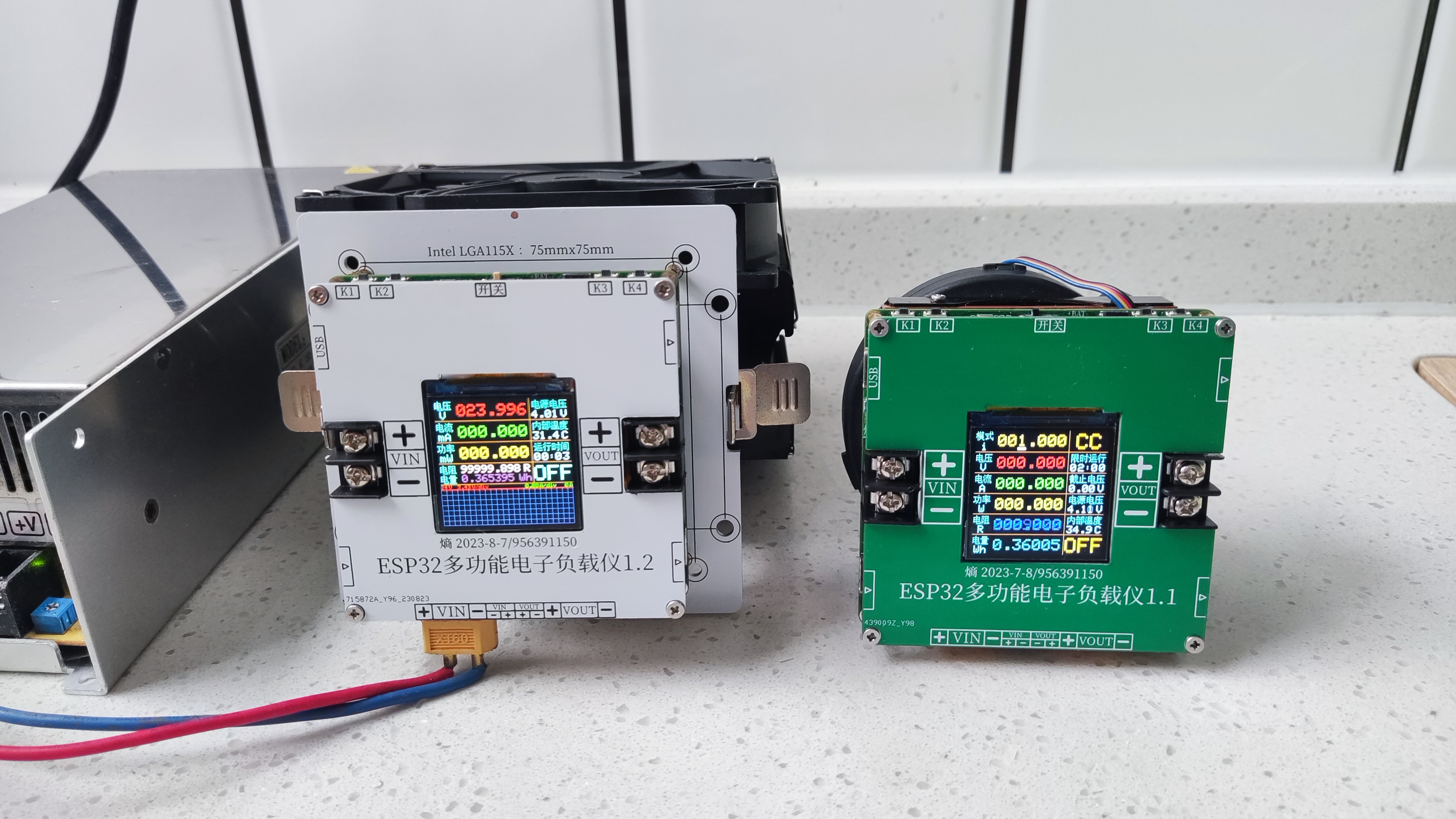
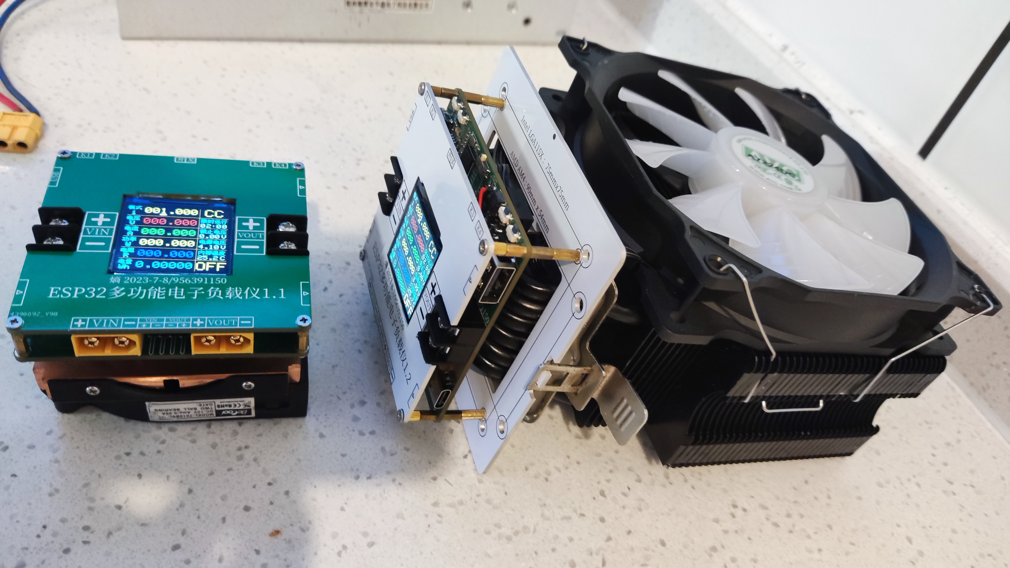
1. ESP32 multi-function electronic load meter is mainly composed of: main control PCBA + TFT + lithium battery + PCB cover + PCB adapter plate + radiator + M2 copper pillar screws. It is assembled according to the 200W plan by default.
2. There are two sets of assembly solutions. The 100W portable solution does not require a PCB adapter board. It requires the use of 4 15mm long M3 screws and the Leopard 1U pure copper CPU side-blown radiator model: LGA115X1U3CC-B.
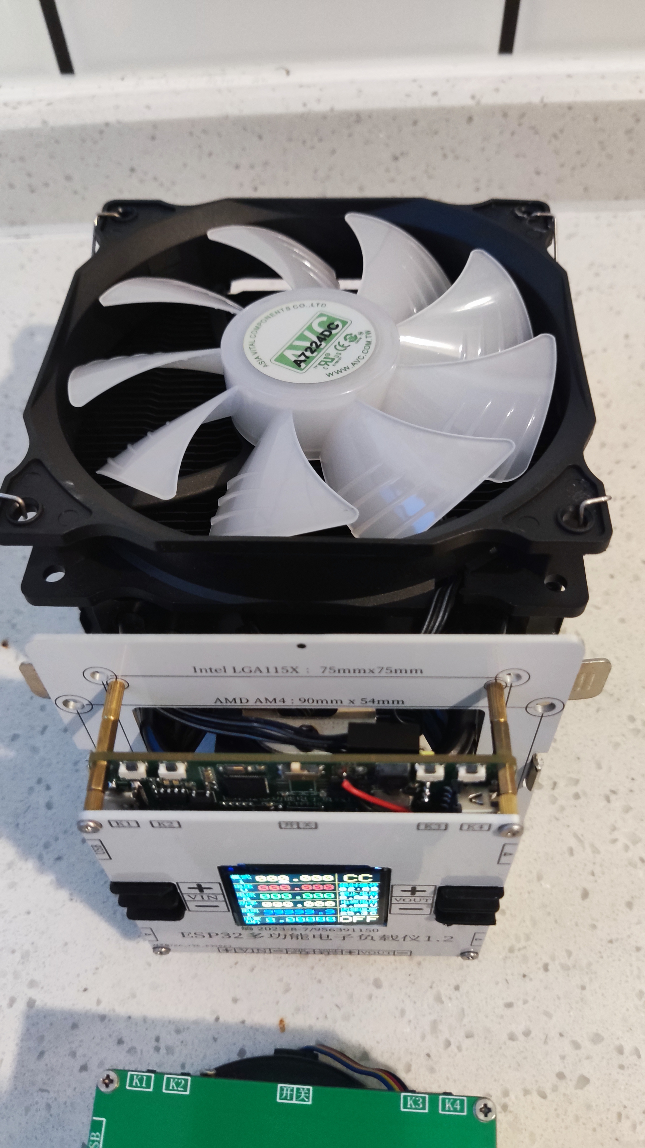
3. The 200W assembly solution requires the use of a PCB adapter board with a high-power CPU radiator that can suppress 200W heat (preferably starting with 4 heat pipes). See the picture for the fixing method.
4. The main control PCBA uses ordinary RF-4 material 4-layer board with a thickness of 1.6mm. It is recommended to use 1.6mm aluminum substrate for the PCB cover and PCB adapter board to ensure structural rigidity. Ordinary RF-4 is also acceptable.
5. TFT uses 1.54-inch 240*240 ST7789V screen model: WA54HC048I-10Z FPC interface 10P 0.5mm pitch.
6. The lithium battery should be an ordinary lithium battery of 604050 specification 3.7V 1800mAh. It is best to use one that can output more than 2A current and be welded to the main control PCB.
7. M2 copper pillar screw connector parameters: single-pass copper pillar (M2*9+3)x4 + double-pass copper pillar (M2*15)x4 + flat head screw (M2*4)x8.
8. The cooling fan supports standard 12V CPU radiator fan and line sequence. Be careful not to connect the pins to the reverse drive power 12V/0.6A.
9. For NTC temperature measurement, it is recommended to use 10K 3950K lead-type NTC and fix it next to the heating power NMOS to obtain real-time temperature.
Announcements
1. When welding PCB, the exposed copper part of the power trace must be piled with tin or buried to reduce the heat and loss of the trace.
2. The connection between the power NMOS and the radiator needs to be coated with thermal conductive silicone grease and tightly fitted to ensure that the heat can be effectively transferred to the radiator.
3. Note that the D pole of the power NMOS is connected to the positive pole of the input and output. If it is connected to the radiator, the entire radiator is also the positive pole. Be careful not to short-circuit the power supply ground.
4. Because the power NMOS is two directly connected in parallel, the automatic current sharing capability of the MOS tube itself is limited, so the same type of NMOS tube must be used. Please refer to the schematic diagram for details.
5. When the input voltage reverse connection or overvoltage protection is triggered, the input protection NMOS will be turned off. The buzzer will prompt that the abnormal wiring must be removed and the device must be restarted to work normally.
6. The input and output directions cannot be reversed, otherwise there is a certain probability that the small current sampling op amp will burn when working in electronic load mode. The default output port does not output.
7. The component parameters are based on the schematic diagram. For components not available in Lichuang Mall, the relevant software and hardware information on Taobao is in the attachment. The schematic diagram has notes and relevant information.
8. This project is CC BY-SA 4.0. If the open source project requires large-scale commercial use, it must be authorized by the original author.
9. This project uses a large number of 0402 package components, which is difficult to hand-solder, or it uses Jialichuang SMT. The project is more difficult to re-engrave according to one's ability.
Physical Display

Designed by 负熵生之光 (from OSHWHub)
Link:https://oshwhub.com/fj956391150/ESP32-shuo-kong-dian-zi-fu-zai-y
Design Drawing
 Empty
Empty
Comment