Editor Version ×
Standard

1.Easy to use and quick to get started

2.The process supports design scales of 300 devices or 1000 pads

3.Supports simple circuit simulation

4.For students, teachers, creators

Profession

1.Brand new interactions and interfaces

2.Smooth support for design sizes of over 5,000 devices or 10,000 pads

3.More rigorous design constraints, more standardized processes

4.For enterprises, more professional users

Completed

PRO MakerLab Electronic Flow Hemp

Electronic Flow Hemp

Project tags

License

GPL 3.0

License: GPL 3.0

Mode:

Mode

Editors' pick

Editors' pick

  • 88
  • 0
  • 0
Update time: 2024-09-29 09:57:11
Creation time: 2024-09-29 02:17:02
Description

Description

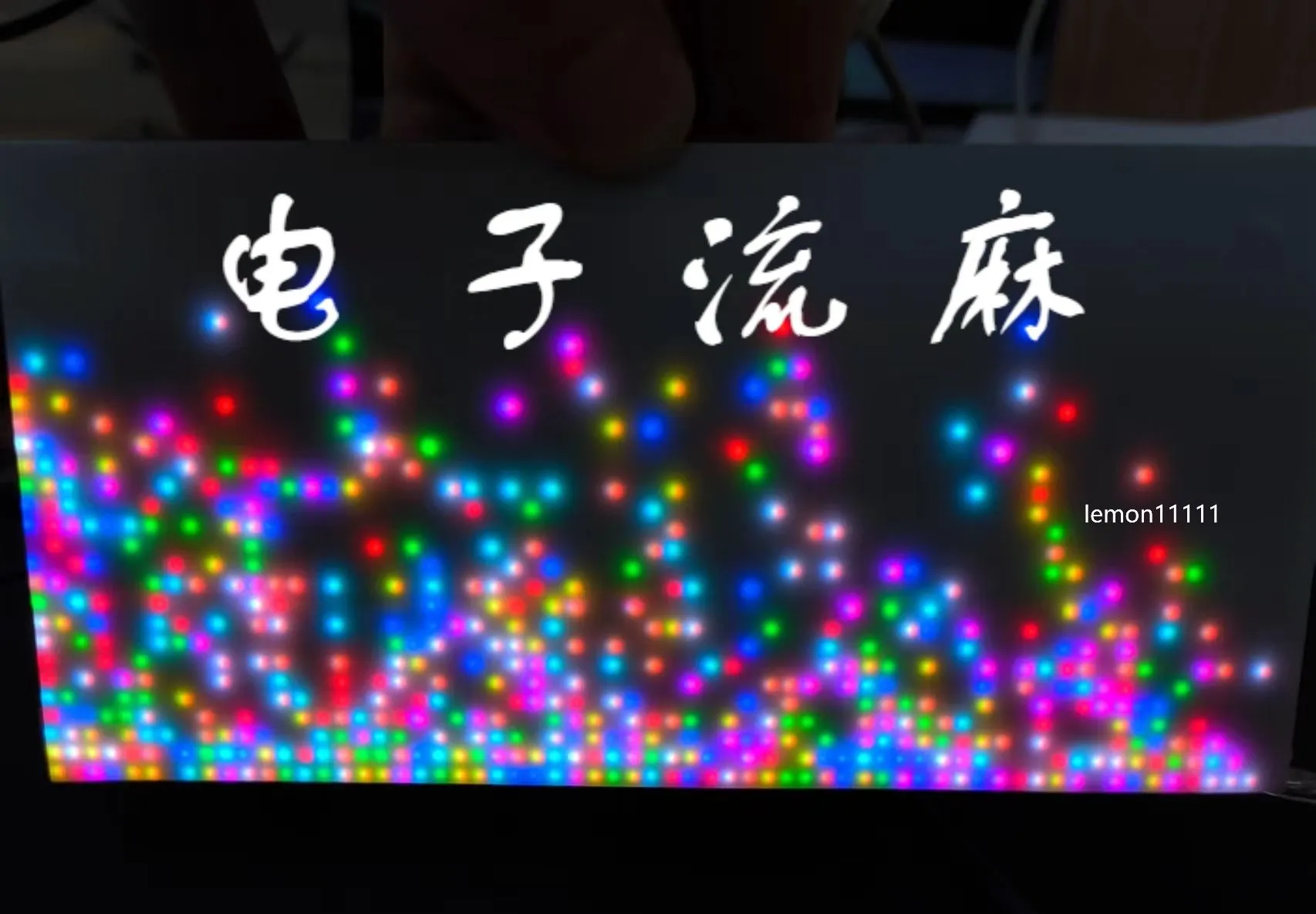
# 1.Introduction I usually like to make various handicrafts, especially quicksand mahjong. I have made many pieces in the past year. This time I wanted to make a special piece of Liuma. I wanted to combine the handicrafts I like to make with the professional knowledge I learned, so I came up with this piece of electronic Liuma. By controlling the on and off of the LED lamp beads, the flow of quicksand in real hemp is simulated. The particles of different colors are intertwined together to create a cyberpunk aesthetic. Please see this video for the specific effect .[I made a piece of electronic hemp! ! ! :](https://www.bilibili.com/video/BV1aze2eaED7/?spm_id_from=333.999.list.card_archive.click&vd_source=7d7556b87d2382aaca7adf3ab2eeba84) # 2.Hardware Part This project is an electronic flow map based on the Lichuang Skystar development board STM32F407. The screen used is a 2.5mm pitch LED dot matrix screen from Weixue with a resolution of 32×64. The MPU6050 module is used to obtain the particles in the electronic flow map. Horizontal and vertical acceleration. The design of the power supply part refers to @小煜哥's IP5306 simple 18650 power bank solution. The IP5306 chip is used to charge a 18650 lithium battery, and the lithium battery is boosted to 5v to power the LED screen and microcontroller. The working principle of this project is: the MPU6050 module obtains the current x-axis and y-axis acceleration, and transmits the collected acceleration data to the microcontroller through the I2C protocol. The microcontroller calculates the positions of all particles based on the acceleration data and displays the results on the LED screen. There is nothing much to introduce in terms of schematic design, just connect the above-mentioned circuits together. The drawn PCB board is as shown in the figure: ![1722131824253.jpg](//image.lceda.cn/oshwhub/f09b1996803d48cc8c38a19377ec003d.jpg) The size of this PCB board is 8mm*16mm, which is exactly the same size as the LED screen. Therefore, put the PCB board below and the screen below. The two can be connected through studs. The position of the studs is as shown in the positioning hole in the picture, which just corresponds to the fixing hole of the LED screen. The two positioning holes in the middle and lower part are used to fix the MPU6050 module, not the screen. ## 2.1 Connection Between LED Screen And Base Plate ![2.jpg](//image.easyeda.com/pullimage/TvBGm9tp3rITTxeA7WbQDNhYbvAqHuDRmY4wlkxN.jpeg) As shown in the picture, a total of two wires are needed to connect the base plate to the screen, one is the data wire and the other is the power supply wire. The manufacturer that sells the screen will come with these two wires, but the supplied wire is very long and may not fit between the base plate and the screen, so it is recommended to use a shorter wire. Shorter data cables can be bought directly on Taobao, but shorter power supply cables need to be rubbed by hand. The data cable has a 2×8p horn socket with a Fail-safe design and will not be connected reversely. Be careful not to connect +5V and GND reversely on the power supply line, otherwise it will burn out. ## 2.2 Connection Between Core Board And Base Board In the core board area on the PCB board, two 2×20p female headers need to be soldered. Be careful not to insert the core board upside down when inserting it into the board. The pin headers of the serial port and download port must face outwards. By the way, the core board is shipped without soldering pin headers. You need to purchase two 2×20p pin headers and one 2×5p pin header for soldering. When welding the core board, the pin headers should be soldered downwards. Be careful not to solder them backwards. There was a Little Hanhan in our lab who soldered the pin headers backwards before. I laughed at him for a long time. Hahaha. Another point is not to solder the core board directly to the PCB board, otherwise it will be difficult to reuse the core board. It would be better to connect the female and pin headers. ![1722132732125.jpg](//image.lceda.cn/oshwhub/f6405886d7354e6a9a17515610346957.jpg) ## 2.3 Connection Between MPU6050 And Baseboard In the MPU6050 area of ​​the PCB board, a 1×8p header needs to be welded. Be careful not to solder the header crookedly, it must be straight. If it is crooked, it will affect the accuracy of acceleration. ![1722132788492.jpg](//image.lceda.cn/oshwhub/e527a20ce7c3457a8f3887a8bc7ee1e0.jpg) ## 2.4 Lithium Battery Charging And Discharging Circuit The chip used in the lithium battery charging and discharging circuit is IP5306. The ground of this chip is connected to the pin under the belly of the chip, so it is difficult to solder. You need to use a hot air gun to solder, not an electric soldering iron. Other parts of the PCB base plate can be soldered using a soldering iron. In addition, the power supply of this circuit board is the type-c interface on the right side of the PCB board, and the type-c interface on the core board cannot be used for power supply. The reason is that the type-c interface on the core board has a small load capacity and the current should not exceed 1A. When the LED screen is fully loaded, the current exceeds 2.5A (of course, the current required for electronic current flow is far from the full load current). According to the information provided by the screen merchant, using the type-c interface of the core board for power supply may burn the core board. . I don't know if the consequences are really that serious, but it must be no problem to use the type-c interface on the right side of the PCB board for power supply. Another point is that the lithium battery box has positive and negative poles. Be careful not to solder them backwards. ## 2.5 Switch The entire PCB board has a total of four key switches, of which the three on the left are not used for the time being and do not need to be soldered. The switch in the lithium battery charging and discharging circuit area on the right must be welded. It is the switch for the electronic current. Short press once to turn on, short press twice in succession to turn off. ![4.jpg](//image.easyeda.com/pullimage/gS6FyOFVVdizAAg0HEKk53KLEviWPssHjqgpcaCZ.jpeg) # 3. Software Part The software part of this project is programmed using keil5 and CubeMX, so the library used is the HAL library. ## 3.1 MPU6050 Module For this part of the program, I referred to the source code of the software I2C reading and writing MPU6050 in the STM32 tutorial of Jiangsu University of Science and Technology. Use the `MPU6050_GetData` function to read the current six-axis gyroscope and accelerometer values. In fact, only two of them are used in this project, namely horizontal acceleration and vertical acceleration. Also note that the SDA and SCL pins used by I2C must be set to open-drain output rather than push-pull output in the program. . . Don’t be like me who spent two days looking for this problem before discovering it. ## 3.2 Define The Structure And Initialize It ```js typedef struct{ float Acce_x; float Speed_x;//Current particle x-axis velocity float Displacement_x;//Current particle x-axis displacement uint16_t Position_x;//Current particle x-axis position float Acce_y; float Speed_y;//Current particle y-axis velocity float Displacement_y;//Current particle y-axis displacement uint16_t Position_y;//Current particle y-axis position uint16_t Color; uint16_t Index; float Random_Acce; }easy_pixel; ``` This part of the code defines some information about a single particle, such as acceleration, speed, displacement, position, color, etc. Initializing the particles is to assign values ​​to the above information of the particles. For example, at the beginning of the video, the pixel blocks are arranged neatly, and the process of coloring them is initialization. ## 3.3 Update the Acceleration, velocity, and displacement of a single particle in sequence We have learned in high school physics that the accumulation of acceleration over time is velocity, and the accumulation of velocity over time is displacement. Or to put it into a more rigorous description, the integral of acceleration over time is velocity, and the integral of velocity over time is displacement. In the program, the integration function can be easily realized. You only need to define a minimum time unit, multiply the acceleration obtained in each cycle by this minimum time unit, and then add them up to get the speed. In the same way, displacement can be obtained by accumulating velocity. When the displacement exceeds 1, it means that the particle should move one grid. ```js void Update_State(easy_pixel* p, float AX, float AY) { Update_Acce(p, AX, AY); Update_Speed(p); Update_Displacement(p); } ``` ## 3.4 Update information of all particles There are a total of 512 particles in this project, which means that by repeating the steps in 3.3 512 times, you can update all the particles at once. The function in 3.4 is written in the while (1) loop, which allows the program to continuously update the status of all particles, and the quicksand can flow on the LED screen. ```js void Update_Group_State(easy_pixel* p, float AX, float AY) { for(uint16_t i = 0;i < Init_Height * Init_Width;i++) { Update_State(p, AX, AY); p += 1; } } ``` ## 3.5 Summary The program block diagram is as follows: ![5.jpg](//image.easyeda.com/pullimage/hzzUxSz6WCvgs7iyCvZwgAsOxlDVhnGyOuIlgk1s.jpeg) I did not add a delay in the loop because it actually took a lot of time for the MPU6050 to read the data, so no delay was needed. # 4. Parts List Here I have listed some components to buy on Taobao. The following are must-buys: * LED screen 2.5mm pitch 32×64 resolution micro-snow dot matrix display RGB full color LED brightness adjustable HUB75 interface DIY screen can be cascaded * MPU6050 module, select the straight pin and solder it down. MPU6050 module three-dimensional angle sensor 6DOF three-six-axis accelerometer electronic gyroscope * One 18650 lithium battery, any capacity is acceptable * The copper pillar series is a bit expensive to buy. * This is used to connect the LED screen and the base plate. I measured that the highest part of the welded base plate is about 25mm, so in theory, any copper pillar with a length of 28-35mm can be selected. I chose 35mm here because I want to put my finger into the gap and press the reset button on the core board M3*35+6 single-head stud. * This is the M3*11mm double-pass copper pillar used to connect the base plate and the MPU6050 module. * This screw is used to fix the copper pillar. Note that the flat head of the screw is a bit large, so only one screw can be screwed on when fixing the MPU6050. Maybe it would be better to use round head screws M3*4mm flat head screws. - A stlink downloader, used to download programs. The following options are available for purchase (the final display effect will be better if you purchase it): - This data cable is used to connect the base plate and the LED screen. 5cm length 2×8p 2.54mm gray cable LED screen connection JTAG download cable - The power supply wire of the LED screen is a little more troublesome. It needs to be welded together with the following two wires. 100mm single-ended wire VH3.96mm pitch color electronic connection terminal wire plastic shell 4P One red and one black 17AWG 1m high temperature resistant super soft silicone wire for model aircraft - LED homogeneous plate, as long as the size is larger than 8cm × 16cm, the thickness can be 0.5mm. The one I bought myself may be a bit expensive, so I won’t post the link. Other components can be purchased on JLC, please be sure to see the components clearly before placing an order! ! Be sure to see the components clearly before placing an order! ! Be sure to see the components clearly before placing an order! ! Don't waste your money by buying the wrong one.

Designed by lemon11111 (from OSHWHub)

Link:https://oshwhub.com/lemon11111/electronic-liuma

Design Drawing

Design Drawing

schematic diagram
1 /
PCB
1 /
The preview image was not generated, please save it again in the editor.
Empty
Project Attachments

Project Attachments

Order File name Download times
1

af1d963d50d1a225dc32d83dfda12385.mp4

52
2

Electronic_Liuma.rar

343
Project Members

Project Members

Target complaint
Related Projects
Change a batch
Loading...

Comment

Add to album ×

Loading...

reminder ×

Do you need to add this project to the album?

服务时间

周一至周五 9:00~18:00
  • 0755 - 2382 4495
  • 153 6159 2675

服务时间

周一至周五 9:00~18:00
  • 立创EDA微信号

    easyeda

  • QQ交流群

    664186054

  • 立创EDA公众号

    lceda-cn