

 Completed
Electronic Components Intelligent Storage Box
PRO Electronic Components Intelligent Storage Box
License
:CC BY-SA 3.0
Description
Project Description
In the field of modern electronic engineering, there are many types of components, especially SMD components. Engineers, especially DIY hardware players, often spend a lot of time finding and positioning these components. For example, I once had to solder one. A very simple PCB board, maybe only 5 components, but I wasted an hour because I couldn't find the corresponding components. Because the components were small in number and not used often, I put them aside. A dark corner. Therefore, in order to improve engineering efficiency and reduce time waste, I designed and developed an intelligent storage solution called "Smart Storage Box for Electronic Components".

Functional topology diagram of electronic components smart storage box project
Features:
1. Intelligent storage and classification: Through the built-in intelligent system, this storage box can automatically identify, store and classify various electronic components, especially chip components. Each component is assigned a unique storage location, keeping the entire inventory organized.
2. Quick search and location: Users can enter relevant information about components, such as models, specifications, etc., through a convenient interface, and the system will quickly locate and display the storage location of the components. This greatly reduces search time in component libraries.
3. Real-time monitoring of component conditions: The storage box is equipped with sensors and monitoring systems that can monitor the quantity and status of components in real time. Users can know the inventory status at any time to ensure sufficient components. When a certain component is insufficient, the system will automatically issue an alarm prompt to remind the user to replenish it.
4. Unlimited expansion of the left and right smart boxes: The left and right sides of the smart storage box are connected to RS485 interfaces, which can be cascaded using wired methods, and the storage box can also be expanded using wireless Bluetooth networking.
5. The height can be reduced freely: Each layer of the smart storage box is connected with spring pins to transmit power and data signals. You can decide how tall the storage box you want according to your own needs. (At present, the maximum height of my design is five layers, and I only need five PCB boards at a time)
6. Data recording and analysis: The storage box records each access to components, and users can query the historical records at any time. This not only helps analyze component usage, but also helps users optimize inventory management strategies.
7. Mobile APP for convenient operation: The storage box is equipped with an intuitive and simple user interface, making the operation more convenient. Users can manage components through the touch screen or connected mobile device.
Application Areas:
1. Electronic hardware development company: Improve the work efficiency of hardware engineers, reduce component search time, and speed up the product development cycle.
2. Electronics manufacturing factory: Manage and optimize raw material inventory to reduce the risk of production lines stalling due to insufficient components.
3. School laboratory: Provide experimental personnel with a convenient and efficient component management method to reduce experimental time and cost.
4. DIY players: There is not much time to integrate and manage these tiny and precise components.
Open Source Agreement
CC BY-SA 3.0.
Project Related Functions
1. Component Storage
- Use your mobile phone to control the light prompts of the component storage bin, store the components in the designated bin, and record their location information.
2. Quick search and positioning:
- Users input relevant information about components, such as models, specifications, etc, through mobile applications.
- The underlying microcontroller STM32 responds to the query request, quickly locates the control system of the storage warehouse and feedbacks the storage location of the components through the mobile phone application.
3. Data recording and analysis:
- The mobile application can store a database and record every access to components.
- Users can query historical records through mobile applications and analyze component usage.
4. Mobile application interface design:
- Provides a user-friendly mobile application interface, including component query, access, inventory monitoring and other functions.
- Achieve stable and reliable communication with the STM32 development board via Bluetooth or Wi-Fi.
5. Auxiliary functions:
- There are 25 RGB lights on the top of the smart storage box, which can be used as a night light, and the color and brightness can be freely switched by rotating the encoder.
- In music rhythm mode, there are two RGB lights on the side of each layer of the smart storage box, which can follow changes in external sounds to form a rhythmic beat.
Project Properties
Original by me.
Project Progress
The underlying hardware and mobile APP software are basically completed, and the functions of the APP software still need to be slightly improved and optimized.
Design Principles
The entire project mainly includes the design of the underlying hardware circuit and the design of the upper-layer APP software. The underlying hardware uses four boards, each of which is responsible for its own control tasks. The upper-layer APP software communicates with the underlying main control board through Bluetooth to realize protocol data interaction between the bottom layer and the upper layer.
1. Underlying hardware design principles
(1) Main Control Board

The main function of the main control board is to prompt the location of components. The schematic diagram uses Renren Technology's WH-BLE106 low-power Bluetooth chip, which supports Bluetooth wireless networking (up to 8 connections). The Bluetooth chip is connected to the serial port 1 of the STM32F103C8T6. After receiving the protocol transmitted from the upper-layer APP, After analyzing the location information of the components, the microcontroller pin outputs a PWM signal to control the lighting or extinguishing of the RGB lights. The location of the components is reminded. Each time, 3 RGB lights are used, which is responsible for reminding which floor occupies 2 , which is responsible for reminding which row and column it is in. The corresponding relationship can be found through the underlying algorithm.
Of course, there are other functions. The core board can allow the OLED display to display Bluetooth connection status, component position display, music rhythm and night light functions, etc.
RS485 wired communication and power cascade are reserved on the left and right sides. 4-Pin spring pins are used for expansion connections using magnetic suction.

3D rendering of main control board
(2) Display Panel

The core board controls the data to be displayed on the OLED display through the IIC protocol. There is also a rotary encoder, which is mainly used as a function button to facilitate switching the functions of the smart storage box of electronic components, and the night light changes color and brightness adjustment through a Rotary encoders can solve all problems and are still very convenient to operate.

3D rendering of display panel
(3) Upper RGB Board

The design of this schematic diagram mainly connects 25 WS2812B lamps in series, which is why I chose this RGB lamp. It only requires three wires (power wire 5V, ground wire, signal wire) to wirelessly expand the RGB lamp, and only Just use a root thread. The signal line here on the upper RGB board is connected to the PB0 pin of the core board, which supports PWM+DMA fast output (TIM3 CH3).

3D rendering of upper RGB board
(4) Back RGB Board

The design principle is similar to the upper RGB board, except that in order to extend the height of the smart storage box for electronic components, spring pins are used for signal lines and power lines to freely connect the upper and lower floors. The signal line here on the back RGB board is connected to the PA6 pin of the core board, which supports fast output (TIM3 CH1).

背部RGB板3D效果图
2. Upper-layer APP Software Design Principles
Android software mainly uses the Bluetooth low-power communication function to interact with data between the bottom layer and the upper layer through a defined data protocol.
The upper-layer software is mainly designed with the following interfaces:
1. Main Interface Function Design
View the overall storage status of the current storage box.

2. Add Component Function Design
Add components and record the physical location of each component. Send location information to the bottom layer for lighting prompts.

3.Detailed Functional Design of Components
View the detailed information of components, perform component removal operations, send location messages to the bottom layer, and provide lighting prompts.

4. All Components Viewing Function Design
In this function, you can view all smart storage boxes for electronic components, including those that have been used before.

5. Functional Design of Component Location Distribution
This function can view the distribution of all components on a floor at once. Click on the corresponding component to enter the component details interface.

6. Search Component Function Design
You can conduct a fuzzy matching search for the required components, and then quickly find and take out the components you need.

7. More Interfaces

8.PCB Project Management
Classify and manage the electronic components required for each hardware project to quickly find the components required in the project and improve efficiency.

Project management capabilities

View project component information
3.Appearance Design
Drawn using SolidWorks software, the overall appearance is as follows.

Assembly front

Back of assembly
Software Description
Wireless communication is carried out between the mobile APP and the underlying device through Bluetooth. The logical operations and data storage of the entire project are basically all on the mobile APP side, because Android can easily add, delete, modify and check the database. It would be too difficult to perform complex storage in the underlying chip. Difficult to operate. All information about components on the Android side is stored in the local database. When we search or store components on the mobile phone, the mobile phone will eventually call Bluetooth communication and send the location and other information of the components to the underlying MCU through the protocol. , the serial port of the underlying MCU connects the Bluetooth device. When the Bluetooth device receives the message sent from the mobile phone, the MCU will perform protocol analysis based on the message to calculate where the component is. Finally, the MCU controls the RGB lighting at that position. Flash reminder. The communication logic between the bottom layer and the mobile phone software is roughly like this, which is relatively simple and easy to understand.
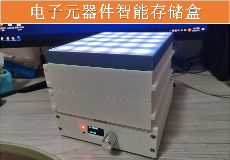
Physical Display
1. Side of smart storage box for electronic components

2. The back of the smart storage box for electronic components

3. Top surface of smart storage box for electronic components

4. The electronic component smart storage box is open

Design Considerations
Due to the tight schedule, this project uses a 3D printed shell, which is relatively slow to print, so it only shows a single smart storage box for electronic components. It is only two floors high. If you want to reproduce it, the maximum is five floors, because the APP software is not It is written to be five stories high. Therefore, a smart storage box for electronic components can store up to 25*5=125 components. Of course, it can be cascaded wirelessly, up to 8 components.
Other
B station video:
Electronic components smart storage box function demonstration video
Designed by WZH66 (from OSHWHub)
Link:https://oshwhub.com/wzh66/tie-pian-yuan-qi-jian-zhi-neng-z
Design Drawing
 Empty
Empty
Comment