

 Completed
DJi drone PSDK development board
PRO DJi drone PSDK development board
License
:GPL 3.0
Description
Project Description
Use the STM32F407 chip to make a DJI PSDK development board and implement simple flight control functions.
Welcome friends to communicate and discuss wechat:dongyu2017 Email:dongyu1009@163.com
The supporting books have been released and can be purchased on all major platforms.

Development boards are also available: DJI PSDK (Payload SDK) development board - Taobao (taobao.com)
Open Source Agreement
GPL 3.0
Project Related Functions
For the E-Port interface design of DJI industrial drones, a PSDK development board is designed with the following functions:
- On-board computer for drones
- Basic drone control
- Waypoint planning flight and control
- Acquisition of image transmission information
Project Properties
This project is made public for the first time and is my original project. The project has not won any awards in other competitions.
Project Progress
At present, the verification of each component has been basically completed, relevant programs can be burned, and communication with the drone has been achieved.
The current development board is an airborne development board designed for the DJI M30T drone.
Design Principles
1. E-Port interface design
In terms of hardware, the E-Port interface is common to the ordinary USB Type-C hardware interface, but the related pin functions need to be redefined. According to the usage requirements, USB Type-C female sockets have many types. The fixing methods include direct plug, horizontal pin, vertical pin and sinking board. The number of pins can be 2pin, 6pin, 16pin and full-featured 24pin.
For the E-Port interface, the Type-C interface with 16p pins can already meet the needs.
Draw the E-Port device and bind the 16pin Type-C package; connect the VCC pin to the VIN network, ground GND and the DET pin used to detect the load connection; connect the serial communication and microcontroller accordingly; and reserve Related interfaces.

2.Power circuit
After inputting the VIN network through the E-Port interface, first connect the power switch and add two 4.7uF and one 0.1uF decoupling capacitors; refer to the design of the E-Port adapter board and add two TVS instantaneous Variable voltage suppression diode to absorb surge voltage and protect the safety of the rear circuit.

3. STM32 circuit design
Including basic reset circuit, clock circuit, download circuit, serial port circuit and startup mode configuration circuit; these circuits are relatively simple, you can refer to the schematic diagram.
4. Design of AHT20 temperature and humidity sensor
Referring to the AHT20 data sheet, the design circuit is as follows:

Software Description
Tip: The software can be nested using code blocks. There is no need to explain all parts of the software, just the important parts.
The software uses DJI PSDK sample software, you can refer to:
https://developer.dji.com/doc/payload-sdk-tutorial/cn/
https://github.com/dji-sdk/Payload-SDK/tree/master
Connect the drone and burn the Bootloader and PSDK sample application into the chip. The output information is as follows:

If the drone is connected normally, you can control the drone through PSDK; for example, the flight control of the drone (running in the diji Assistant2 software):

For specific operating effects, you can view the attached video.
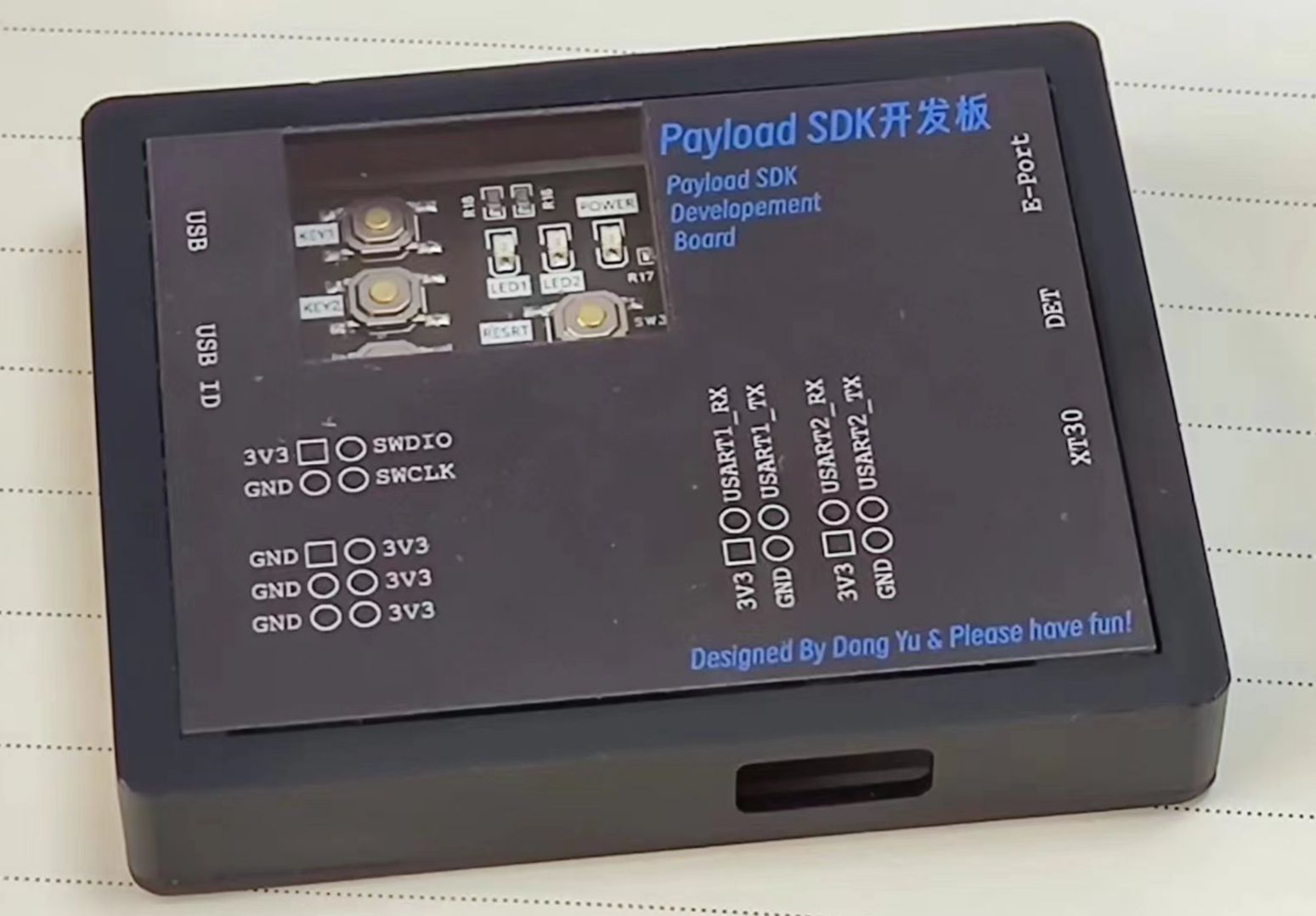
Physical Display
The physical picture of the circuit board is as follows:


(1) The interfaces for connecting the drone and debugging equipment are designed on the left and right sides respectively to facilitate connection and debugging;
(2) There are 4 screw holes around the board for connecting the PSDK bracket and fixing it on the drone.
Of course, you also need to set the shell for it, the same in JLC proofing.


The front part here is made of Imagine Black material, while the bottom part is made of ordinary nylon spray paint, which has a better effect. However, it is a bit thin because the front is dug down, but fortunately there are panels to support it:

Here I made two types of acrylic panels, black and white. The functions of each interface and the definition of pin headers are identified above.
The complete installed body is as follows:

Design Considerations
When designing, be sure to connect the DET pin of the E-Port to ground, otherwise the drone will not be able to recognize the development board.
Designed by dongyu1009 (from OSHWHub)
Design Drawing
 Empty
Empty
Comment