

 Completed
Design of intelligent farmland remote data acquisition and management system
PRO Design of intelligent farmland remote data acquisition and management system
License
:GPL 3.0
Description
Version: Starting from April 1, 2024, this manuscript will be written on the evening of May 17, 2024
Updated related open source source code and documentation on May 20, 2024: STM32_MAKE is the actuator part, and STM32-G is the data acquisition part.
Specific physical exercise [Smart Agriculture - Automatic Farmland (Greenhouse) Remote Data Collection and Management System] https://www.bilibili.com/video/BV1qf421m769/?share_source=copy_web&vd_source=d3c8fab68214f4bb12e2aa4ac6c162e3
Chapter 1: Project Description
1.1 The process of topic selection
January 3, 2024, choose a topic.
It was proposed at the meeting that you can choose your own topics, both algorithms and hardware.
I had learned about a direction before: using the inverse design method to design optical integrated devices. In the end, I chose to do hardware. I saw similar projects on the open source platform, so I chose this topic.
Modified project requirements on January 11, 2024
1.2 Project related functions
Get straight to the point and introduce the requirements for project design.
The design is mainly aimed at the greenhouse planting environment. It combines key technologies such as the Internet of Things to design and implement a smart farmland remote data collection system, which can grasp the growth environment of crops faster and more accurately, and implement corresponding unmanned management based on the collected data. , complete functions such as automatic irrigation of farmland and insulation of greenhouses. The system consists of two parts: hardware construction and software design. The hardware construction can collect farmland environment data units and control units, and the software design can real-time monitor and control the startup and working mode adjustment of the irrigation system.
(1) Farmland environment monitoring and control functions
The system consists of two parts: hardware and software. In terms of hardware design, the core controller monitors the working status of the equipment through sensors and collects environmental parameters such as soil temperature and humidity, air temperature and humidity, and carbon dioxide concentration in the farmland environment. It also has an irrigation circuit to control the water outlet system and adjust the water supply according to the water demand of crops.
(2) Remote monitoring range of the system
Upload farmland environment data to the cloud server wirelessly to realize data transmission between hardware equipment and terminal software to achieve remote monitoring and control.
(3) Terminal software Web interface development
Remote real-time monitoring is performed through the Web interface terminal, and operations such as starting and stopping the equipment and working mode adjustment can be remotely controlled.
(4) Design of emergency system
Design an emergency response system under extreme circumstances and farmland disaster early warning in the system to monitor the occurrence of various events in real time and be able to issue alarms according to preset rules so that corresponding emergency measures can be taken in a timely manner. Avoid crop losses.
(5) Solar charging
The system has a solar charging circuit that requires no external power supply and can achieve self-sufficiency in power supply for hardware devices. For remote or large-area farmland.
Chapter 2: Project Progress
April 1, 2024
Survey the needs of farmland (greenhouse) environment and determine system functions.
Data collection part: Use sensors to collect climate data of farmland (greenhouse), and collect necessary environmental information for crops in the farmland (greenhouse) in real time, such as air temperature, air humidity, soil moisture, light intensity, carbon dioxide concentration and other data into the data collection part within the terminal.
Actuator processing part : Automatically control irrigation, ventilation, heating, lighting and other functions according to changes in farmland (greenhouse) environmental parameters.
IoT cloud platform: Receives and stores equipment status and collected data. Users can achieve remote real-time monitoring, control the startup of the actuator system, and adjust the working mode through the mobile app or web interface.
Solar charging and power supply module: No need for external power supply or external transmission cables, it can achieve self-sufficiency in power supply for hardware equipment, and is suitable for remote or large-area farmland.
April 8, 2024
Start looking for relevant projects that you can refer to, learn hardware development knowledge, and build hardware circuits.
The solar charging circuit and power module circuit are here based on Aknice 's [RA ] farmland environment data wireless collection and irrigation self-discipline system (based on Renesas MCU ). I would like to thank my predecessor for the open source. At the same time, the project address is attached: [RA] Farmland environment data wireless collection and irrigation self-discipline system (based on Renesas MCU) - JLC EDA open source hardware platform (oshwhub.com).
April 15, 2024
While waiting for the hardware module to arrive, learn the knowledge of the esp8266-01s module and the development of the Alibaba Cloud IoT platform. It is intended to solve long-distance wireless transmission and upload the detected farmland environment data to the Alibaba Cloud IoT platform.
April 17, 2024
The hardware modules arrived and system design began. The implementation function is as follows:
Data collection part: The function is shown in Figure 2-1. Relative soil humidity Soil: 5.34%, relative light intensity 41.87%, air temperature and humidity t: 24, h: 64%, carbon dioxide concentration CO2: 400ppm, volatile organic matter TVOC: 0ppb.

Fig 2-1: Preliminary implementation display of data collection part
The executor processing part implements the following functions:
The buttons are independently controlled to turn on and off the irrigation, air sprinkler, simulated fill light, heating, ventilation, and alarm function modules.
April 16, 2024
Alibaba Cloud IoT platform settings and hardware connections to the IoT platform.
Create a product: smart agriculture test, create the device: mqtt-stm32 under the product, create the object model as shown in Figure 2-2, and use value-added services to create a Web interface.

Fig 2-2: mqtt-stm32 object model
April 17, 2024
The initial design of the solar charging circuit, the voltage can reach 21.1V, roughly verifying the feasibility of the plan. Pay attention to the size of the designed PCB battery box. I did not pay attention when verifying the solution, so the battery box cannot be placed on the PCB.

Figure 2-3: Initial design of solar charging circuit
April 18, 2024
Design schematics and make PCB for verification.
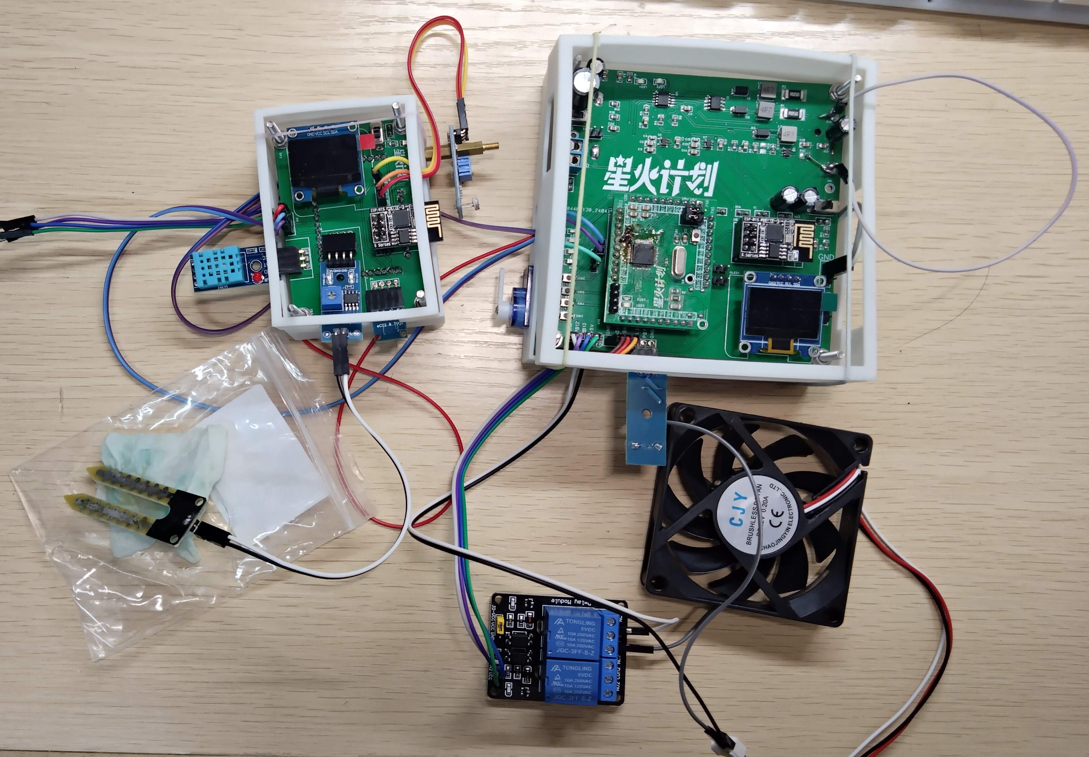
Preliminary physical objects: 
Fig 2-4: Solar charging and control actuator part

Figure 2-5: Part of the actual data collection
April 27-May 5, 2024
I went out for three days and started to perfect the project and write reports. The effect is currently as follows:

May 10, 2024
The project has come to an end.
Chapter 3: Design Principles
3.1 Overall design architecture of the system
According to the functional requirements of the smart farmland remote data collection and management system, this system designs an environmental data collection system solution. It deploys various sensors such as air temperature and humidity, soil moisture, light, and carbon dioxide at the sensing layer, and transmits the collected data through the network layer. The wireless WIFI technology and MQTT protocol transmission module are uploaded to the application layer. The application layer is the Web interface of the computer Alibaba Cloud IoT cloud platform, which displays the detected farmland environment data and the status of the control system actuator equipment, and generates history Data trend graph for easy observation and reference.

3.2 System hardware framework

3.3 Schematic diagram
(1) Core board
SFor the design of the minimum system of STM32F103C8T6 microcontroller, draw a minimum system according to your own ideas.

For the real thing, two pieces were welded. This one was not welded well and there was a weak welding part. I refused to admit defeat and had to weld it three times before using it.


(2) Hardware schematic diagram of data acquisition part
The data acquisition part mainly consists of five modules: microprocessing module, various sensor modules, WIFI wireless communication module, USRT serial communication module and power supply module. The schematic diagram of the data acquisition part is shown in the figure below.
In the design of the data collection part, the STM32 microcontroller is used as the core part, responsible for the data analysis and collection of various sensor devices in the farmland (greenhouse) remote data collection and management system, and uploads it to the cloud platform and UART serial communication module through the WIFI module. The WIFI module and actuator handle part of the communication. Each sensor module makes a selection based on the environmental data that needs to be collected, and also considers the way the microprocessing module reads the data. The WIFI module is a bridge for communication with the cloud platform, which completes the upload of environmental data. UART serial port communication is to send data information to the actuator processing part and WIFI module through the serial port for communication.


(3)Hardware schematic diagram of actuator processing part and power supply part
The actuator processing part mainly consists of five modules: microprocessor module, each actuator equipment module, UART serial communication module, WIFI wireless communication module and power supply module. The principle of the actuator processing part is shown in the figure below.
In the design of the actuator processing part, the STM323 microcontroller is the core part, responsible for detecting the working status and battery power of each control module and uploading it to the cloud platform through the WIFI wireless communication module, and receiving information sent from the data acquisition part through UART serial communication. and process it. Each actuator module is responsible for executing the instructions of the microcontroller, such as watering, lighting, ventilation, heating and other functions. UART serial communication is to receive data information from the data acquisition part. WIFI wireless communication is a bridge with the cloud platform, uploading the status of the controller device to the cloud platform and receiving control instructions related to the cloud platform.
In the power supply part, the common lithium battery voltage is 3.7v. Taking into account the needs of system design, the power supply part mainly consists of three parts, namely the photovoltaic solar panel BUCK step-down circuit, the BOOST boost circuit of 5V equipment such as relays, and the 3.3V microcontroller. device's LDO buck circuit. As shown below.


Notice:
(1) When drawing the PCB, the core board is drawn by yourself. If you buy the STM32 minimum system finished product directly, remember to replace the PCB of the main control microprocessor .
(2) The power supply of the fan is 12V, and a boost module needs to be added in combination with a relay to power the fan.
Assemble finished product.
Chapter 4: Terminal cloud platform system design
Define the basic information of the product on the Alibaba Cloud IoT platform, product name: Smart Farmland Remote Collection and Management System, and establish two node devices under the product directory, namely the STM32_WIFI_1 device for data transmission and the STM32_WIFI_1 device for operation execution. STM32_WIFI_2 device of the device.
The next step is to define the object model in the product. The object model of data collection and actuator involves air temperature (temp), air humidity (humi), relative light intensity (LightLux), soil relative humidity (soilHumidity), carbon dioxide (co2), Volatile organic matter concentration (HCHO), watering (sgp30), heating plate status switch (hot), fan status switch (fan), simulated fill light status (led1), air sprinkler status light 2 (led2), work light transition status (led). See the table below for specific types.
 The web interface is designed like this.
The web interface starts from the upper left, followed by the working status of the device. Red indicates abnormal operation and green indicates normal operation; real-time battery; alarm function; blue indicates normal and red indicates alarm; three real-time voltage curves are used to display the latest three Environmental data changes within hours; six dashboards are used to display real-time data; system working mode and the setting of the five actuator functions on and off; the working status of the actuator equipment, blue means off, yellow means on; additional Device location map and device management functions.
Chapter 5: Core Code Description
System development uses the hal library of the STM32CubeMX development software, combined with KEIL5 to write and compile the system code. Code burning uses ST-Link as the burning tool, and is combined with the serial port Ai-Thinker assistant software for physical debugging.
The software system design part of the system design mainly includes the software system design of the hardware module and the design of the terminal software Web interface, which runs through the collection, transmission, monitoring and operation process of the entire system. The design process is shown in Figure 5-1.

Fig 5-1 Software system design block diagram of the hardware part
Below I mainly introduce the software system design of the hardware module. The hardware part of the smart farmland remote data collection and management system is controlled through the program running inside the STM32 microcontroller. The STM32 microcontroller 1 obtains the information collected by each sensor and processes it, uploads the farmland environment data to the cloud platform and detects whether the environmental data is Turn on the function and send it to STM32 MCU 2. MCU 2 executes each actuator and also uploads the transition state of each actuator device to the cloud platform. The software design process of the smart farmland remote data collection and management system is shown in Figure 5-2:

Fig 5-2: Software system design flow chart of hardware modules
The specific design of the hardware module software system of this system includes the configuration of timer polling, the serial port 1 communication configuration used between two microcontrollers, the serial port 2 communication configuration used for WIFI wireless transmission, and the DMA multi-channel ADC to read soil moisture and light Intensity configuration, ADC detects solar charging voltage and battery voltage configuration, IIC reads the carbon dioxide and volatile organic compound concentration configuration in the SGP30 sensor, GPIO reads the temperature and humidity configuration of the air in the DHT11 sensor, IIC communication method OLED displays the status of the actuator, GPIO Control LED fill lights and relays to realize heating and ventilation, aerial sprinkler, SGP30 watering and buzzer alarm control logic configuration.
The use of STM32 microcontroller for the system's microprocessor determines what development tools are used to design the software part. The software system development of the hardware part of the system uses the hal library of the STM32CubeMX development software, combined with KEIL5 to write and compile the system code. The code burning uses ST-Link as the burning tool, and combines the serial port Ai-Thinker assistant software for physical debugging.
The wireless transmission part of the system uses lightweight publish/subscribe message MQTT transmission protocol technology. The MCU initializes the ESP8266-01s wireless transmission module that uploads data to publish and subscribe messages to the Internet of Things platform, and then sends the obtained data each time. Farmland environment data is transmitted to the IoT cloud platform through the MQTT protocol every 5 seconds.
Chapter 6: Software and Hardware Debugging
After the system is designed with both hardware and software, the overall system is tested. The test is divided into hardware facility testing and Web terminal interface testing.
The hardware facilities include whether the farmland (greenhouse) environmental data collection is normal, whether the serial communication between the two STM32s is normal, whether the control and status identification of the actuator equipment are normal, and whether the WIFI wireless transmission module uploads data to the computer terminal Alibaba Cloud IoT Cloud Check whether the MQTT protocol communication of the platform is normal, whether the photovoltaic solar cell BUCK circuit of the power supply, the BOOST boost circuit of 5V equipment, and the LDO step-down circuit of 3.3V equipment are normal and can maintain self-sufficiency and stable operation.
The Web terminal interface debugging of Alibaba Cloud IoT platform uses mqtt.fx to simulate the MQTT client to publish and subscribe messages. The wireless transmission module ESP8266-01s publishes and subscribes messages to the products of the IoT platform through AT commands. Finally, the wireless transmission module ESP8266-01s is verified. Whether the upload of farmland data using MQTT protocol can be successful and updated in real time, whether historical trend graphs can be generated normally, and whether actuator equipment can display working status and be controlled on the web interface.
Chapter 7: System physical test results
7.1 System remote environmental monitoring and actuator function implementation
7.1.1 Implementation of data collection function
Modules participating in the environmental detection function include air temperature and humidity sensor, soil moisture sensor, light intensity sensor and SGP30 gas sensor. Each module works normally and displays environmental parameters on the cloud platform, indicating the normal operation of the environmental monitoring function. The following is the specific testing process:
(1) Complete the hardware assembly of the data acquisition part of each module and connect it to the power supply part.
(2) Turn on the LAN wireless network, start the power supply, and check the initialization of each module through the display module of the data collection part.
(3) Open the Alibaba Cloud IoT platform, check the device connection status in the product, enter the device to view the object model data, you can view the real-time data of the object model, or click on each object model data to view historical data.
(4) Enter the Web interface, where you can visually view real-time data and historical data.
The results displayed on the Web interface are shown in Figure 7-1 below. The system uploads several environmental parameters collected from the on-site environment in real time. The left side of the figure shows the data changes of the six environmental parameters within the latest three hours, and the right side shows the six Real-time data on environmental parameters.

Fig 7-1 System physical test remote environment data collection web interface
For each environmental parameter, recent data curves can be viewed uniformly on the cloud platform, and suitable growth environment parameters for crops can be studied from the changes in the parameter curves. As shown in Figures 7-2 to 7-7 below.


After testing the system, the data collection function of the system can operate normally. Real-time remote monitoring of the farmland (greenhouse) environment can be achieved through the designed Web interface, and the ambient air temperature, air humidity, light intensity, soil moisture, and carbon dioxide concentration can be obtained. and volatile organic compounds and other necessary environmental information for crops.
7.1.2 Implementation of actuator function
The user implements the functional module of the farmland actuator through the system on the Web. This time, the actuator servo, relay, and fill light are used for simulation. Each actuator works normally under the control of the microcontroller, and the device working status is displayed on the cloud platform Web interface, indicating the normal operation of the control function. The following is the specific testing process:
(1) Complete the hardware assembly of the actuator processing part and connect it to the power supply part.
(2) Turn on the LAN wireless network, start the power supply, and check the working status of the actuator through the display module of the actuator processing part.
(3) Open the Alibaba Cloud IoT platform, check the device connection status in the product, enter the device to view the object model data, you can view the real-time status of the object model, or click on each object model data to view the historical status.
(4) Enter the Web interface, and you can visually check the working status of the actuator device and the voltage of the battery in the designed interface.
The control and status physical test display interface of the system actuator function is shown in Figure 7-8 below. Blue means off and yellow means on.

Fig 7-8 Actuator function control and status physical testing
The battery voltage and overall equipment working status of the actuator part are shown in Figure 7-9. The red color of the device indicates that the device is working abnormally, and the green color indicates that the device is working normally and is currently in a normal working state. The battery voltage is 3.7V and the power supply is normal. When the environment changes to extremes, the system's alarm function will also be turned on. Red means the alarm is on, and blue means the alarm is off.

Fig 7-9 Battery voltage and overall equipment working status of the actuator part
The system can set the control data flow of the actuator through the Web interface. The microcontroller decodes the received data and then controls the switching value of each actuator. After the actuator completes the corresponding operation, the status of the actuator will be uploaded to the Web interface. Show it.
When executing control instructions on the Web interface, there are problems such as network transmission. After the entire function of the actuator is realized, there will be a time delay of 1s-5s, but this delay will not affect the normal operation of the actuator.
7.1.3 Implementation of the system’s automatic watering, temperature and lighting adjustment functions
Data collection and execution are communicated through UART serial port to realize automatic watering, temperature and lighting adjustment and other functions. The actual system test web interface is shown in Figure 7-10. In the working mode, manual control is turned on. The bright yellow color in the working mode indicates that the receiving mode has been turned on. In the web interface, the air sprinkler is turned on, and the fill light transition light turns yellow and does not turn off automatically ( The web interface remains blue and the hardware fill light is turned on). Turn on automatic control in working mode, shine the light towards the light sensor, the fill light transition light will automatically turn blue, and the hardware fill light will be turned off.

Fig 7-10 System test web interface
Function real-life video effect.
Chapter 8: Summary and Outlook
The following obvious problems are summarized below:
With the addition of video surveillance equipment, if you want to add cameras and wireless video signal monitoring, the deployment of wireless video signal monitoring can monitor the growth of crop entities. I have bought a camera module, but currently the communication protocol involved in the system cannot transmit video signals, and the things I have learned cannot be added to the camera. If there is an opportunity to add a camera later, we will discuss it at that time.
Secondly, I would like to thank the platform for its support. grateful! ! !
Finally, this is the first-generation version. It is the first time for many things to be touched. There are many things that were not considered carefully during the design, such as the need for 12V voltage to power the fan, the Dupont line is messy, and the sensor positions are not well distributed. Reasonable issues. To this end, I have also thought of many solutions. For example, some modules can be integrated into the board, such as relays, 2V boosters, core boards, WiFi modules, etc., or they can be made into a board. Although this project is not perfect or excellent, it has also become a symbol for me to verify my own ability. Maybe one day in the future I will come back and see this project, and I will make improvements and design it better based on my strength at that time.
Here I say that the future is promising, and, sir, I really want to make progress.
Ends on May 17, 2024.
Designed by cc122921 (from OSHWHub)
Design Drawing
Intellectual Property Statement & Reproduction Instructions
This is an open-source hardware project. All intellectual property rights belong to the creator. The project is shared on the platform for learning, communication, and research only; any commercial use is prohibited. If your intellectual property rights are infringed on EasyEDA, please notify us by submitting relevant materials in accordance with the Rules for Complaints and Appeals of IPR Infringement.
Users must independently verify the circuit design and suitability when replicating this project. All risks and consequences are borne by the user, and the platform assumes no liability.
 Empty
Empty
Comment