

 Completed
Design of high frequency adjustable signal source based on STM32
PRO Design of high frequency adjustable signal source based on STM32
License
:GPL 3.0
Description
Project Description:
This project intends to design a high-performance, multi-functional DDS-function waveform signal generator to achieve the basic functions of the project, while the module scalability is strong.
The basic function of this design is to realize the output of sine, triangle, square wave and arbitrary wave, and the amplitude and frequency of the waveform are adjustable. OLED is used to display waveform parameters and output status and waveform selection. Refer to the demo video for specific function details.
Among:
The core of the system waveform generation is composed of AD9910, which is mainly used to generate triangle waves, square waves and other arbitrary waveforms. There is no need for other peripheral circuit structures except the filter circuit. The system control core is STM32F407ZG, and the display screen is a 2.8-inch OLED touch screen. The waveform parameters are adjusted through three EC11 horizontal encoders.
In addition, high-frequency circuits generally use: immersion gold technology, metal edging, and multi-layer board design. All are used in this design. In actual development, the cost is not reduced, and double-layer board design is mostly used. Therefore, actual project needs require Depends on cost.
It should be noted that DDS chips are generally very expensive. For example, AD9910 and AD9959 are around 200. One way to save costs is to use disassembled chips, which cost dozens of dollars, which can greatly reduce costs! ! ! !
Project Related Functions:
With the AD9959 and AD9910 modules as the core, the following basic functions are implemented::
1.10Hz~4200MHz signal frequency control, amplitude control, and phase control functions.
2. Triangular wave output.
3. Square wave output.
4. Arbitrary wave output.
5. Waveform output frequency and amplitude are adjustable.
Note: Please refer to the demonstration video for specific function details.
Project Properties
This project is made public for the first time and is my original project. The project has not won any awards in other competitions.
Project Progress
Time: 2023.10.1----Current progress: The design of the AD9959 module has been completed, the relevant waveform output debugging of the module has been carried out and the waveform function output is in line with expectations.
Time: 2023.10.19----Current progress: The AD9910 module design has been completed and is waiting for the board to be delivered for testing.
Time: 2023.10.25----Current progress: Testing AD9910 performance.
Time: 2023.11.19----Current progress: End of test.
Screenshot of Function Demonstration:


Design Principles
1. AD9959 schematic design description.
The data sheet of the AD9959 is in English. I did not read the details carefully. High-frequency circuits have higher requirements for power supply filtering and isolation. This is very important. The circuit was designed with reference to some typical design schematics, and was expanded from 4 outputs to 8 outputs, because each channel of AD9959 has expanded a reverse waveform for verification. In the AD9959, the filtering circuit is mainly performed through magnetic beads, and the circuit structure is as shown in the figure.

The power circuits used by Taobao are generally AMS1117 series LDO chips. The 1.8V power conversion part of this type of LDO will heat up seriously when in use, so it is replaced by TMI1007B in this design. The circuit structure is as follows. Actual verification shows that it can greatly reduce serious heating problems. However, among the two PCBA circuits produced by SMT, one of them cannot be used. It is most likely because the quality of the chip purchased is not good! You still need to be more careful when buying this on Taobao.

2. AD9910 schematic design description
When designing the AD9910 schematic diagram, the data manual has a Chinese version, so the circuit design reference is the Chinese version of the design, the design reference for the power part follows the above power grouping principle, please check the schematic design for details, not much explanation here
Software Description
Matlab code description for generating arbitrary waveforms. The following screenshots are screenshots taken using matlab when generating arbitrary waveforms.


Please see the attachment for Matlab and STM32 codes. Only a brief explanation is given here. Please note the red text in the screenshot above. The waveform parameters cannot be negative and cannot be greater than 16383!
Physical Display:
①.Module DDS-AD9959 module:

Immersed gold hemming! ! ! ! Very nice.


②. Physical display of module DDS-AD9910 module:


When laying out the AD9910, its layout structure is very friendly and does not require a large amount of fan-out to complete the layout of the data lines, which is unmatched by the AD5595.
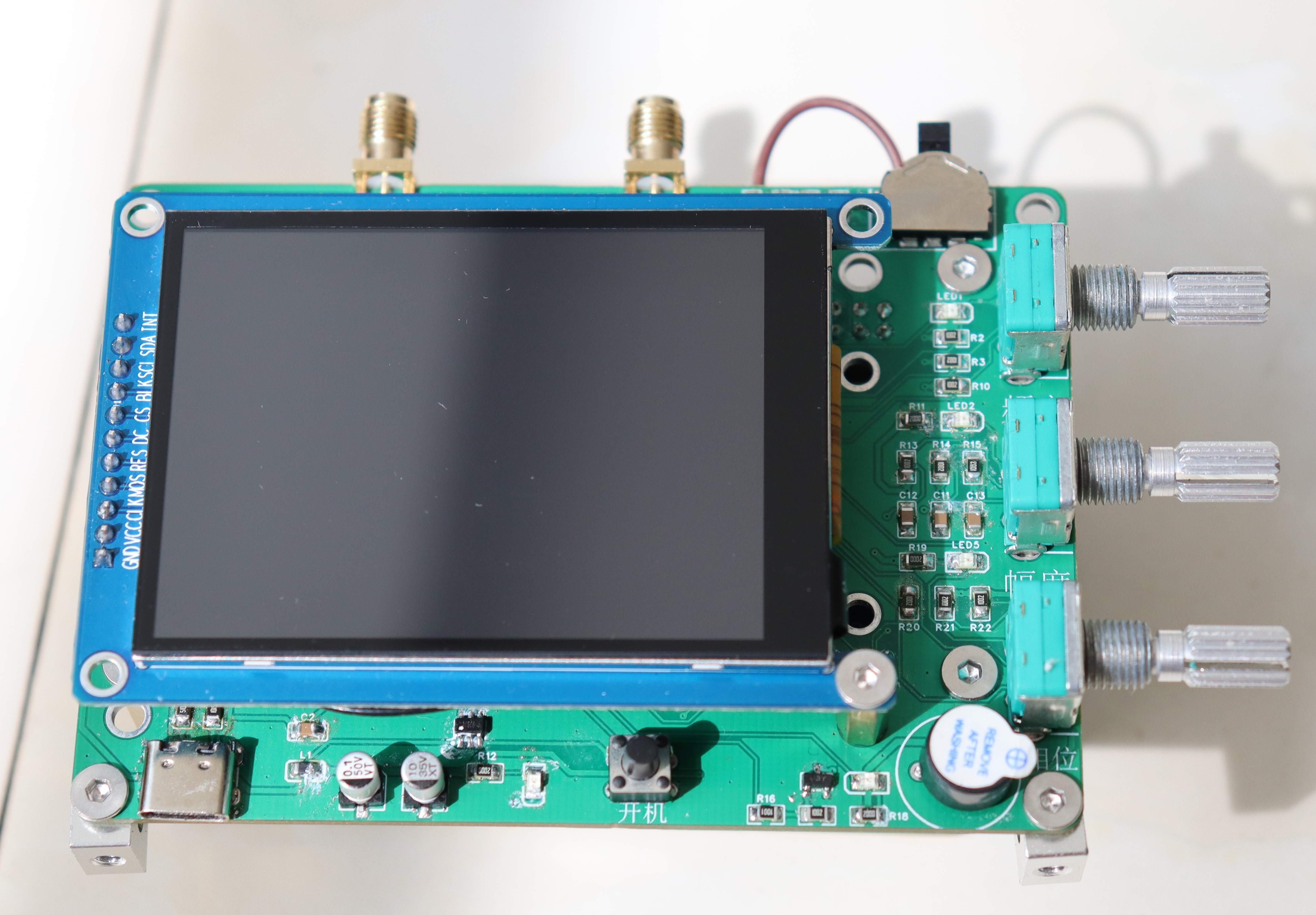
③. Overall system physical object


In addition, high-frequency circuits generally use: immersion gold technology, metal edging, and multi-layer board design. All are used in this design. In actual development, the cost is not reduced, and double-layer board design is mostly used. Therefore, actual project needs require Depends on cost.
It should be noted that DDS chips are generally very expensive. For example, AD9910 and AD9959 are around 200. One way to save costs is to use disassembled chips, which cost dozens of dollars, which can greatly reduce costs! ! ! !
Design Considerations:
1. For the high-frequency signal source module, the DC-DC circuit used should use a multi-channel DC-DC chip, otherwise the LDO will be seriously heated. The circuit used in this design, at least, will not burn your hands after the LDO is powered on and running for a long time.
2. For LSQP packaged chips, it is recommended to use SMT. Some problems with hand soldering are difficult to find, but SMT sometimes has problems. For some chips that are difficult to solder and are not available in LC Mall, it is recommended to go to Taobao to find a reputable chip. And it is an original and genuine supplier , because only one of the two SMT boards of AD9959 and AD9910 can be used! ! ! Because the DC-DC chip cannot output the 1.8V level normally. That means the power conversion chip is bad...
3. For the high-frequency signal board, it is recommended to adopt a multi-layer board design, choose the immersion gold process, and carry out edge wrapping to achieve the best power coupling effect and reduce external interference.
4. The generation of arbitrary waveforms requires a certain understanding of the generated waveforms, such as amplitude and frequency parameters, and the operations are all implemented through the internal registers of the AD9910, which requires a certain basis for register operations.
Demonstration video: https://www.bilibili.com/video/BV1bN411u7sT/
Designed by 许欢颜 (from OSHWHub)
Link:https://oshwhub.com/cheerfulness/mu-ni-xin-hao-bo-xing-xian-shi-f
Design Drawing
 Empty
Empty
Comment