

 Completed
Ceramic filament clock 1.0
PRO Ceramic filament clock 1.0
License
:GPL 3.0
Description
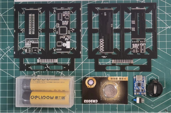
Hardware Part
Circuit part: Main control circuit module, digital tube module and digital tube connection base respectively. The main control circuit is the 51 microcontroller control part, which includes the 51 microcontroller minimum system, clock control and digital tube control circuits. The digital tube module display light uses ceramic filament, so this project is called "ceramic filament clock".
Other parts: battery, clock circuit backup battery, lithium battery charging module and power switch.
PCB Part
The digital tube display part is composed of two two-digit digital tubes and a stopwatch display. The digital tube is connected to the main control circuit by another PCB board.
There is a digital tube bit selection circuit in the connection board, where 1 and 3 are connected to the first digital tube, and 2 and 4 are connected to the second digital tube. When the four-digit clock is displayed, because the two connecting boards are connected to both sides of the main circuit board, the bit selection can be 12 or 34. Only when making an eight-digit clock display, the two connecting boards need to be connected together and they need to be distinguished.
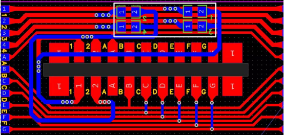
When selecting a bit, you can connect it directly, or you can weld a resistor or an adjustable resistor, etc. Because there is no automatic brightness adjustment function, after many verifications, I soldered a 270 ohm resistor here (I personally think this brightness is just right for me). You can decide according to your own needs.
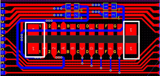
When displaying four digits, the seconds do not need to display the seconds, only the two middle ones need to flash. As shown in the figure below, the control end of the second display near G can be directly connected to G. The common end of the second display near 1 needs to be connected to an unoccupied bit of 1234 at the board connection. Here is the digital The tube location selection is the same, but leads are required.
There is also a small section in the PCB file for downloading the circuit, but due to lack of time recently, this circuit has not been empirically tested. You can ignore or remove it. If you have time, you can help test it. Also, if PCB proofing is not free and you need to pay for trenching, you can take out the intermediate control circuit, connection circuit and download circuit and reassemble them at home.
Program Part
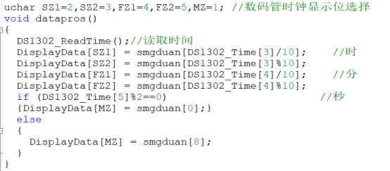
There are two places that need to be modified in the program. The others can be left alone unless it is used for eight-digit display. One place is the selection of the digital tube display bit, and the other place is the time setting.
The selection of the digital tube position is determined by the selection of the digital tube position on the hardware circuit connection board. Here you can directly download the "Nigital Tube Position Display" program and enter it to display it directly, as shown in the figure below. Then change uchar SZ1=2, SZ2=3, FZ1=4, FZ2=5, MZ=1; in the main program according to the displayed numbers, as shown in the figure below. Because the seconds display does not display numbers, you need to manually search it. You can change the value of MZ=1 and download it to see if the seconds flash.
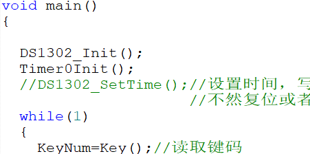
The program to set the time DS1302_SetTime(); This line of code is the program to write the time. This line of code needs to be written in two situations. One situation is that there is no time program in the DS1302 chip. The second situation is that the code in the DS1302 chip is disordered, such as power failure and restart without a backup battery. Therefore, after writing the time program, you need to comment out this line of code and write the code again to lock the time. Otherwise, the time will be written again when the time is reset or powered off and restarted, and the time retention function cannot be realized.
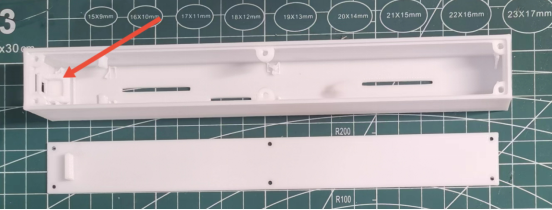
Shell Part
The shell is 3D printed and divided into a shell and a base. The base and shell are fixed with injection molded copper nuts (2*3.5*2) and screws (M2.5). Another important thing to note is that when installing the power switch, you need to use hot melt glue to fix it.
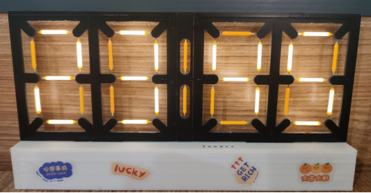
Effect Demonstration
Because of the size of the video, it cannot be uploaded here. If you need to watch related videos or tutorials, you can go to the B station with the same name (Electromechanical Cai Xiaobai) and search for it on the homepage to see it.
Video connection: Ceramic filament clock, 51 microcontroller control version. _bilibili_bilibili.
Change Log
May 14, 2023, a program to set the brightness dimming at night was added.
May 14, 2023, added a new shell base model, previously uploaded as if the screw hole position is a little different, corrected and updated.
May 14, 2023, the component material table of the PCB board was added.
May 30, 2023, Added the total bill of materials.
June 22, 2023, the PCB board display reverse program was added
June 22, 2023, Added a burning software file.
Designed by 机电菜小白 (from OSHWHub)
Design Drawing
 Empty
Empty
Comment