

 Completed
Call for |3D printer peripherals
PRO Call for |3D printer peripherals
License
:CC BY-NC-SA 3.0
Description
Blibili Demo link: https://www.bilibili.com/video/BV1Fa4y1G76h/?vd_source=a1e9502e385d1bb03fa3ea7d653e93a3
Front row tips: When buying Taobao chips, you must think twice, there are not many fakes! I bought 3 copies of MP3302, a total of 15 pieces, but none of them worked! It's all burned! It can only be driven by the display module that I bought before!

Directory:
1. Introduction
2. Hardware design
3. Software design
4. Future planning
1. Introduction
First of all, thanks to the following information providers, without their sharing and dedication, many projects are only utopian, not realized, I believe that in the future, our open source environment will get better and better, like me who is not from a professional class can also play, after all, open source is sharing and learning!

2. Hardware design
Monitoring board:
The main control uses ESP32 S3, which originally wanted to use the chip instead of the module, but considering the reproduction threshold of the students, the module method is adopted, with a 565RGB screen interface on board, a constant current LED driver screen backlight (due to the existing LED constant current backlight chip to buy a fake, so the module is used to drive the RGB screen) passive buzzer, SHT30 temperature and humidity monitoring, up to 4M serial port download speed.

Secondary curing machine:
The advantages of using Espressif's ESP32C2 (i.e., ESP8684) chips are: low crystal frequency requirements, integrated FLASH, and low peripheral circuit requirements. A total of ESC input interfaces, 1 12V UV lamp driver interface, 12V LED lamp driver interface, 12V fan interface, and a TVOC detector are designed. At the same time, there is also a knob screen serial port communication (to be completed), so that the interaction of the knob can also be fed back into the secondary curing machine. The DCDC step-down design is adopted, and the 12V is stepped down to 5V to power the serial chip, and then the LDO is stepped down to 3.3V to supply power to ESP32 and other chips.

3. Software Section
1. Monitoring board
Programming with ESP-IDF, using LVGL as the graphical UI, double buffering, by modifying the ESP-NOW example so that it can communicate via WIFI LAN/Bluetooth, and can parameterize/observe each peripheral, is the brain responsible for this project. PlatformIO programming is adopted, and the underlying layer of PlatformIO, that is, ESP-IDF5 programming, comes with various drivers, which is convenient for programming.
There are 5 parts in total.
1.Blynk
I used the self-built server approach. You can also use the master station of Blynk, but the control will be relatively few, you need to charge money to get the right to use some firmware, if you use the self-built method, the control that can be used is similar to the master station, the energy is still unlimited, you can use the control at will.
Next are the steps to install Blynk-server.
First of all, prepare a server in your home LAN (because it is easier to set up), I use ROCK5B, which is a smart device central control system at home, installed with Ubuntu20.04.
(1) Enter the terminal page, which is generally shown in the following figure.

(2) Pull the blynk-server build file, here I put it on gitee.
Terminal inputgit clone https://gitee.com/lin_xiaoyan/blynk-local-server.git,display the following.

The instruction file has been pulled to your server, use it to enter the directory, use the ls command to view the contents of the directory, if it is displayed, it will be fine.

(3) Initial operation
Go to the directory and runjava -jar server-0.41.16-java8.jar -dataFolder /home/pi/Blynk -serverConfig /home/pi/someFolder/server.properties,You'll find an error. It doesn't matter. Just follow the steps below.
Note that the first data directory address is/home/pi/Blynk You need to create a new folder using the mkdir command. Mine is in /home/rock/Blynk, this is not dead, you can also create a new folder in blynk-server, and then use the pwd command to view the location of the directory, fill in the directory.

The second directory address is the server's parameter setting directory, you need to create a new server.properties file in the directory you set, I used the vim tool to create a new one, in the someFolder directory, enter the following command vim server.properties, and then enter: wqto complete the creation of the file.

When the settings for creating a new directory and creating a file are completed, the following screen will appear when you run java -jar server-0.41.16-java8.jar -dataFolder /home/pi/Blynk -serverConfig /home/pi/someFolder/server.properties it again.

Open the https://10.0.8.14:9443/admin, 10.0.8.14 is the IP address of the intranet, fill in the intranet address where your server is located to see the following interface, if you want to use it on the external network, you need to do intranet penetration in the future.

The email and password obtained from running the program above can be seen as follows.

Our Blynk needs to run in the background.
Run crontab -e, which is a Linux task table, and execute commands at regular intervals.
Choose 2 vim.
Enter @reboot java -jar /home/pi/blynk-server.jar -dataFolder /home/pi/Blynk (the directory here needs to be changed).

Execute
sduo service cron reload
sudo service cron restart
You can close the page.
Congratulations! The blynk-server has been built!
I use a millet ball for inner net penetration, and here I thank the stabbing ball boss! Free servers available!
First, register an account in the following tutorial (https://blog.xiaomiqiu.com/article/121).
Put the Mi Ball client into your server directory.
My server architecture is arm64, so I save the linux-arm folder to my server directory.

Use vim xiaomiqiu.conf to configure your Mi Ball server.
Generally shown like this, I hid the auth_token and server_addr.

auth_token can be found on the Mi Ball console.

server_addr can find https://manager.xiaomiqiu.com/forum/question/questionDetail/39 in the list of Xiaomi Mi Ball servers, if you use the free number, then you don't need to modify it.

After the configuration is complete, execute ./xiaomiqiu_start.sh and press enter.
If it's running in the background, you'll need screen. ubuntu: sudo apt-get install screen ; centos: yum install screen.
Then screen -S
A new screen will appear
Then execute ./xiaomiqiu_start.sh, press enter, and finally press ctrl+A+D to switch out of the page.
At this point, the blynk-server is built. Log in https://ngrok.xiaomiqiu123.top:Allocated mapping port/admin and the following interface will appear, congratulations!

Next, go to the mobile server configuration.

Click on the traffic light below to look at the above page, click custom, enter the ngrok.xiaomiqiu123.top, the next line is the port, just fill in the mapped port.

The following page will appear! However, you need to create a new device on your mobile phone and click on User->admin@blynk.cc on the blynk web client.
Scrolling down will bring you the following information.

Among them, we want to write down the Token.
Next, let's go to the device side to write the software.

As you can see, blynk has a function of begin, which means that it is initialized, and the BLYNK_AUTH_TOKEN in front of it is a string of characters that we just got on the web side. IPAddress is the private address of your server.
At this point, the Blynk is partially complete.
2.ESP—NOW
ESP-NOW is a wireless communication protocol defined by Espressif Systems that enables direct, fast, and low-power control of smart devices without a router. It is capable of coexistence with Wi-Fi and Bluetooth LE, and supports multiple SoCs such as Espressif's ESP8266, ESP32, ESP32-S, and ESP32-C. ESP-NOW is widely used in smart home appliances, remote control, and sensors.
ESP-NOW is a wireless communication protocol based on the data link layer, which simplifies the OSI upper layer protocol of Layer 5 into one layer, so that data transmission does not need to go through complex layers such as network layer, transport layer, session layer, presentation layer, application layer, etc., and there is no need to add packet headers and unpacket layers in turn, which greatly alleviates the lag and delay caused by packet loss when the network is congested, and has a higher response speed.
ESP-NOW is easy to configure and simple to initialize, and only needs to configure the callback function for receiving and sending to communicate.
We can see the initialization here.

The first is the initialization of the nvs_flash, which is a requirement of the wifi library, and if there is no one, an error will be reported.
The second is the initialization of the esp_now, which can be called directly, and if the initialization is wrong, an error will be reported.
Then there are two callback functions, namely OnDataSent1 and OnDataRecv, which represent OnDataSent1: the callback function after executing the esp_now_send of the sending function (that is, the program executed after running), and OnDataRecv: the callback function that is executed whenever data is received.

As you can see, we receive the callback function and use memcpy to copy the data of incomingData (i.e., the data sent by the sender) to the Data structure through the function memcpy.
Generally speaking, we just need to register this function, and the above is the canonical way to write the callback function.
Then let's take a look at the structure of Data, which is actually called by both sending and receiving functions, which will facilitate the standardization of data transmitted in both directions.

If you open the code on the sender, you can see that their ESP-NOW transceiver structure is the same, which is what I call data standardization, because the data on the structure must be the same for each segment, and the order and size occupied in memory are also the same, which is conducive to our data invocation and discrimination.
In this thread, I keep sending commands, and when esp_now I receive data, esp_err_t result1 = esp_now_send(broadcastAddress1, (uint8_t *) &Data, sizeof(Data)); I call the receive callback function, so that the child completes the bidirectional transmission between the two devices.
This is the printing of the sending and receiving data of the main control board.

3. RGB interface 7 inch screen
This is the ESP-IDF routine, and one of the advantages of using PlatformIO is that you can call the ESP-IDF routine, and you can also call the Arduino library, because the underlying layer is actually the same, and this method also applies to STM32, where the underlying layer is cubemx.
It is worth noting that the setting of these parameters has to ask the screen manufacturer, otherwise the driver will fail.

4. LVGL
There is nothing to say about the initialization of LVGL, the ESP-IDF routine, create a thread, and call the swipe function.

The development tool I use for LVGL is gui-guider.
Here I will talk about how to port the code of gui-guider to our device.
First of all, after we have developed the UI page, we will see the following important files when generating the C code.

setup_scr starts with the page you set up, which contains various obj initialization functions, we just need to copy the files starting with gui_guider.c, gui-guider.h, and setup-scr to the directory of our device code.
Some students may have asked, event_init.c is not needed?
Actually, this is the initialization function of lvgl time, but some controls GUI-guider do not have the setting of this event on it, so I am hand-rubbing the event, and I don't need to event_init the code inside;
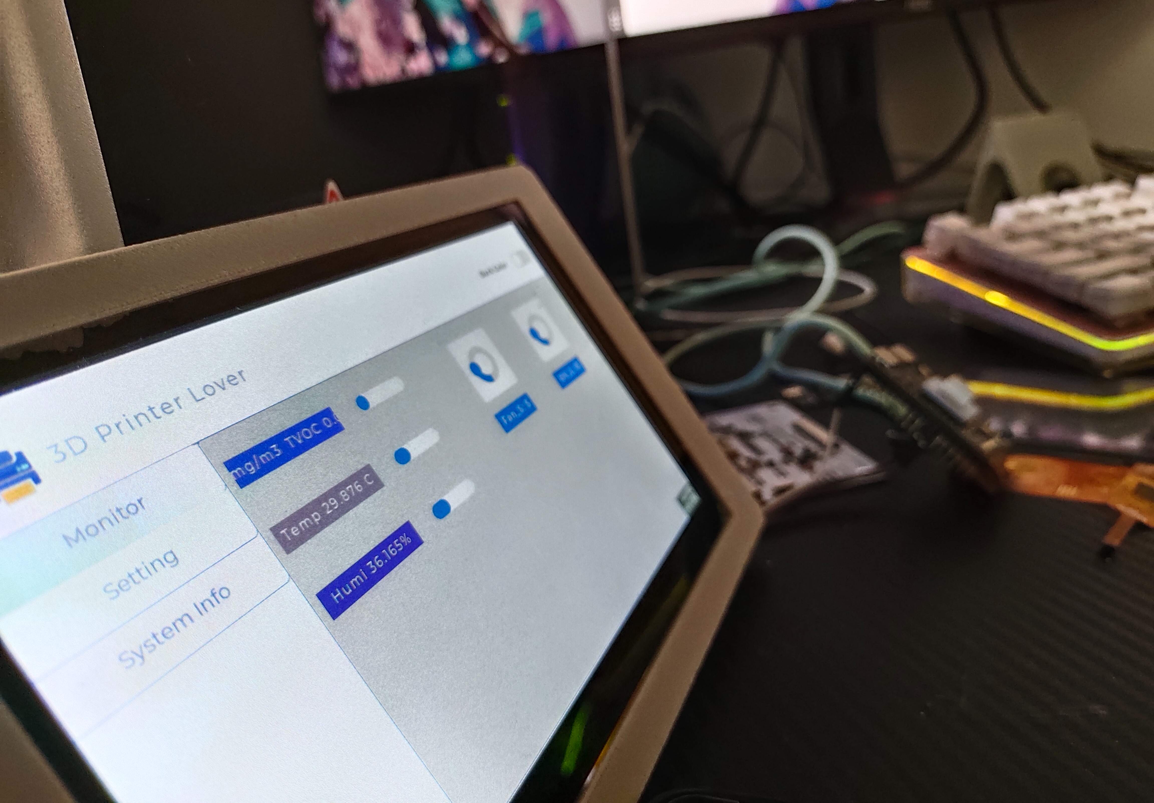
And then the transplant is done is this effect.

5. PWM generation
I use the routine of ESP-IDF, in fact, Arduino is simpler, only need to set up 3 steps ledcAttachPin(uint8_t pin, uint8_t chan)、ledcSetup(uint8_t chan, uint32_t freq, uint8_t bit_num) to complete the initialization, through ledcWrite(uint8_t chan, uint32_t duty) to complete the duty cycle setting, but I haven't studied how to assign timers, So I use the ESP-IDF program.
And the ESP-IDF PWM routine is like this, it is not called PWM, but LEDC.

The first is the CHANNEL setup, configuring the PWM CHANNEL, assigning pins, output polarity, initial duty cycle, and PWM speed mode.

Next is the time-base configuration, which should be noted in the duty_resolution item, which will be discussed later.
Then it's time to initialize the timebase, and the output channel.
At this point, the PWM initialization is complete.
Pass
ledc_set_duty(ledc_mode_t speed_mode, ledc_channel_t channel, uint32_t duty);
ledc_update_duty(ledc_mode_t speed_mode, ledc_channel_t channel);
In these two functions, we can modify the duty cycle, but rely on the duty_resolution to determine the value we set.
For example, if I have LEDC_TIMER_13_BIT here, the resolution of this channel is 13bit, and when the duty cycle is 100%, duty = 2^(13)-1=8191.
Why is it called resolution, because with each change of duty cycle, the duty that can be changed increases, so each change in duty cycle will become more delicate (this can be seen on the LED)
If we want a duty cycle of 50%, then we need to set it to 50/100* [2^(13)-1] = 4095, and the PWM wave generated is shown in the figure below.

6. Capacitive touch
Used Mr. Chen Liang's integrated driver, Mr. Chen Liang is a big guy who plays the screen, the famous GFX library is written by him, and Station B also has a number, you can pay attention to a wave~
The LVGL registered touch driver looks like this.

After the callback function is written.
Initialization would be fine if it was written.

2. Secondary curing machine
Using ESP-IDF for programming, through ESP-NOW, it can communicate with the monitoring board, and can be sent to the mobile phone through blynk, so as to obtain the parameters of the environment, and the parameters can be set on the blynk, and the main control board is then sent to the secondary curing machine, so that the parameters of the secondary curing machine can be modified, and at the same time send information to the monitoring board, so that the data on the monitoring board can also be updated in real time.
The ESP-NOW and PWM drivers are similar to the main control board, so I won't repeat them here.
The next thing to write about is the driver of the SHT30 and TVOC sensors.
1.SHT30 temperature and humidity sensor.
Old friends, expensive and inaccurate.
Driven via I2C.
The first is the I2C initialization route.

When invoking, it returns to the initialization state, and returns ESP-OK to have been initialized, it is worth noting that there is already an I2C pull-up here, and theoretically you can not add a pull resistor.

The I2C write data is as above, because our SHT30 is also to be initialized, we can use the above steps to set up the SHT30 initialization.
It can be written like this in the code.

The sending procedure is the same as that on ESP-IDF.

Reading data is similar to writing data, except that the write function is replaced by a read function.

Finally, the verification is complete.

2. TVOC sensor
Initialization is done through the following steps.

As you can see, the first thing is to set the uart, and then the next thing is to initialize the driver, allocate RAM space, and divide the pins to be OK.

Since the ESP32 has no receive interrupt, we can only set the timing to receive data, while the TVOC sensor sends data once in 1 second, so we can set it to a smaller receiving period than him.

According to the manual, we need to find the header of the corresponding string in the receiving data character, which is similar to the fingerprint module driver, first of all, we receive data into the array, and then search for the address pointer of the string below the header through the strstr function, and then point to the address, at this time the address is the address of our TVOC data.

Through the validation function, the obtained data is our TVOC data string.

3. FDM environment collection (future planning)
To be uploaded.
4. Light-curing cleaning machine (to be integrated)
4. Future planning
1. Due to the 30-day internship, the part of FDM monitoring cleaning machine was not completed, and I will make up these two parts in the follow-up after writing my graduation thesis. The cleaning machine uses neodymium magnets and motors to rotate, and the effect looks okay.
2. Study the way of SPIFFS+LVGL to store data, at present, the data does not have a storage function, and it will be added later.
3.3D print shell online ing~
4. Since the RGB drive of ESP32-S3 7-inch screen is already the limit, the follow-up will consider using Allwinner T113 to drive.
Progress tracking.
On March 16, the basic UI graphics were about to be completed, and the Alibaba Cloud device was connected.


On March 17, SmartConfig network configuration has been completed, and there is no need to manually enter the WIFI password in the program.

On March 19, the functions of LED stepless dimming and TVOC sensor were completed.
Designed by lin_xiaoyan (from OSHWHub)
Design Drawing
 Empty
Empty
Comment