

 Completed
【 Blue Bridge Cup 】 The 13th Blue Bridge Cup microcontroller design and development project national competition
PRO 【 Blue Bridge Cup 】 The 13th Blue Bridge Cup microcontroller design and development project national competition
License
:GPL 3.0
Description
1. Project Introduction
The 13th Blue Bridge Cup MCU Design and Development Project National Competition, based on the four-ladder/Guoxin Changtian MCU competition training platform provided by the organizing committee, modified the configuration according to the requirements of the competition, and drew a practice training board that meets the basic requirements.
2. Hardware block diagram
Figure 1 is the hardware block diagram in the description file, which is mainly divided into single-chip microcomputer, button, pulse, ultrasonic, LED, AD/DA, E2PROM, and digital tube display.

Fig.1 Block diagram of system hardware
3. Detailed explanation of the module
According to the hardware block diagram of the competition description file, the configuration is carried out with reference to the device package of the CT107D MCU competition training platform, and the hardware schematic diagram is deleted and modified on the basis SCH_of the hardware schematic diagram in the DIP_SCM_2022 directory in the electronic resource data package of the 13th Blue Bridge Cup Competition. Don't make too many changes, try to be compatible with the official training platform of the Blue Bridge Cup.

Fig.2 CT107D MCU competition training platform

Fig.3 SCH_CT107D MCU competition training platform V20

Fig.4-1 V30_MCU of the SCH_CT107D MCU competition training platform
![]()
Fig.4-2 V30_USB_SerialPort of the SCH_CT107D MCU competition training platform

Fig.4-3 V30_P0_EX of the SCH_CT107D MCU competition training platform

Fig.4-4 V30_USER of the SCH_CT107D MCU competition training platform

Fig.5 SCH_ the national competition of the 13th Blue Bridge Cup single-chip microcomputer design and development project
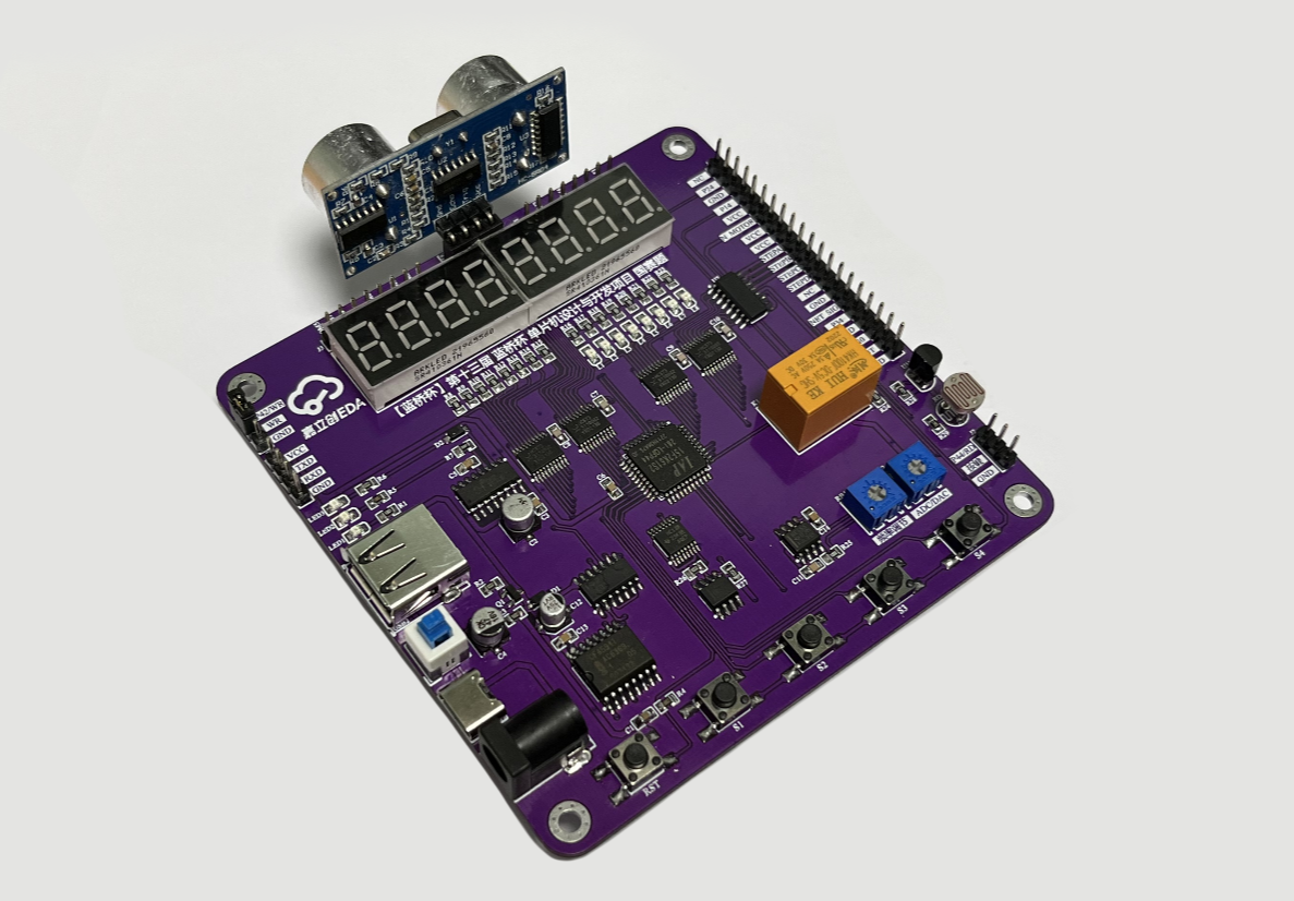
- MCU chip: The main control MCU uses the IAP15F2K61S2 chip designated by the Blue Bridge Cup MCU Competition;
- Power Module:DC power socket and TYPE-C, provide 5V DC power supply;
- Control buttons: keep four buttons to realize the switching, addition and subtraction of interface parameter modes;
- Display module: realize the mode status prompt function through LED indicator;
- Digital tube module: The digital tube display uses a 0.36-inch common yang digital tube for interface display of frequency, humidity, distance and other parameters;
- Ultrasonic module: The ultrasonic circuit is modified and replaced with the HC-SR04 module, which simplifies the circuit and is easy to use, and the ultrasonic sensor realizes the ranging function;
- Signal generation module: NE555 pulse signal generation circuit is composed of a pulse signal generation circuit to generate the pulse signal required for the experiment;
- ADC/DAC module: The AD/DA conversion circuit measures and adjusts the output voltage of the potentiometer through the PCF8951 ADC/DAC channel;
- Storage/IO expansion: E2PROM uses AT24C02M to count the number of relay switches and save the data in the address;
- MM/IO mode channel selection: 74H138 decoder and 74HC02 NAND gate device, WR and P42/WR short-circuit MM mode; WR is shorted to ground in IO mode;
- Program download: onboard USB to serial port function, which can complete the serial communication and download between the single-chip microcomputer and the PC, and also leave the pin header download interface;
- Other modules: relays, photoresistors and temperature sensors required for the competition, extended pin headers and M3 screw holes;
4.Bill of materials
|
BOM_ the 13th Blue Bridge Cup MCU Design and Development Project National Competition |
||||||
|
NO. |
Name |
Parameter |
Device designation |
Quantity |
Encapsulation |
Item number |
|
1 |
Resistance |
1kΩ |
R1,R8~R23 |
17 |
R0805 |
C17513 |
|
10kΩ |
R2,R4~R6,R24,R26~R29 |
9 |
C17414 |
|||
|
510Ω |
R3 |
1 |
C17734 |
|||
|
300Ω |
R7 |
1 |
C17617 |
|||
|
100Ω |
R25 |
1 |
C115423 |
|||
|
2 |
Capacitance |
1uF |
C1 |
2 |
C0805 |
C111768 |
|
100nF |
C3,C5,C6,C11,C13,C14 |
6 |
C1711 |
|||
|
10pF |
C7~C10 |
4 |
C157608 |
|||
|
47uF |
C2,C4 |
2 |
SMD,5x5.4mm |
C129414 |
||
|
10uF |
C12 |
1 |
SMD,D4xL5.4mm |
C72484 |
||
|
3 |
Potentiometer |
50KΩ |
RB1 |
1 |
RES-ADJ-TH_3362P
|
C81264 |
|
10KΩ |
RB2 |
1 |
C118956 |
|||
|
4 |
Photoresistors |
GL5528 |
RD1 |
1 |
RES-TH_L5.1-W4.3-P3.40-D0.5 |
C125627 |
|
5 |
Switching diodes |
1N4148W |
D1~D3 |
3 |
SOD-123 |
C2099 |
|
6 |
MOS tubes |
SI2301 |
Q1 |
1 |
SOT-23-3 |
C2891731 |
|
7 |
DC power outlets |
DC-005-25A |
DC1 |
1 |
DC-IN-TH_DC005 |
C136715 |
|
8 |
USB connector |
TYPE-C |
USB1 |
1 |
USB-SMD_KH-TYPE-C-2P |
C2919656 |
|
TYPE-A |
USB2 |
1 |
USB-A-TH_USB-302-T |
C86461 |
||
|
9 |
Microcontroller |
IAP15F2K61S2 |
U1 |
1 |
LQFP-44 |
C47451 |
|
10 |
USB chip |
CH340C |
U2 |
1 |
SOP-16 |
C84681 |
|
11 |
Latch |
74HC573PW |
U3~U6 |
4 |
TSSOP-20 |
C5944 |
|
12 |
Darlington transistor array |
ULN2003ADR |
U7 |
1 |
SOIC-16 |
C7512 |
|
13 |
Timer |
NE555 |
U8 |
1 |
SOP-8 |
C434480 |
|
14 |
Analog-to-digital conversion chip ADC |
PCF8591 |
U9 |
1 |
SOIC-16 |
C8366 |
|
15 |
EEPROM |
AT24C02M |
U10 |
1 |
SOP-8 |
C356696 |
|
16 |
Temperature sensor |
DS18B20 |
U11 |
1 |
TO-92 |
C376006 |
|
17 |
Decoder |
SN74HC138PWR |
U12 |
1 |
TSSOP-16 |
C157527 |
|
18 |
NOR |
SN74HC02DR |
U13 |
1 |
SOIC-14 |
C350559 |
|
19 |
LED |
Red light |
LED1,LED4,L1~L8 |
10 |
LED0805 |
C84256 |
|
Green light |
LED2 |
1 |
C84260 |
|||
|
Blue light |
LED3 |
1 |
C84259 |
|||
|
20 |
DISPLAY |
4 position 0.36 "common anode |
DS1,DS2 |
2 |
LED-SEG-TH_12P |
C132660 |
|
21 |
Keystroke |
SMD 6*6mm |
RST,SW1~SW4 |
5 |
SW-SMD_4P |
C455113 |
|
Self-locking 7*7mm |
SW2 |
1 |
SW-TH_6P-L7.0-W7.0-P2.00 |
C318863 |
||
|
22 |
Relays |
HK4100F |
K1 |
1 |
DIP-6 |
C12072 |
|
23 |
Pin header |
1x4P in-line |
J1 |
1 |
HDR-TH_4P-P2.54 |
C2691448 |
|
1x3P in-line |
J2,J7 |
2 |
HDR-TH_3P-P2.54 |
C49257 |
||
|
1x8P in-line |
J3,J4 |
2 |
HDR-TH_8P-P2.54 |
C706880 |
||
|
1x20P in-line |
1 |
HDR-TH_20P-P2.54 |
C429964 |
|||
|
24 |
Female header |
1x4P in-line |
J5 |
1 |
HDR-TH_4P-P2.54 |
C2718488 |
|
25 |
Ultrasound module |
HC-SR04 |
J5 |
1 |
HDR-TH_4P-P2.54 |
|
|
26 |
Studs |
M3 |
M1~M4 |
4 |
M3 |
C551322 |
5. PCB design
The size of the board is controlled within 10*10cm, the layout reference is shown in Figure 6, the DC power socket, USB connector and each expansion interface are placed on the edge of the board, the digital tube is placed on the top, and the keys are arranged under the board. Add silk screen printing and LOGO annotations, and place M3 screw holes at the four corners for fixing the support.

Fig.6 Layout reference view
Provide the following reference suggestions in the wiring: set the power cable to 30mil, make it as bold as possible, and set the signal cable to 10mil width; In the process of wiring, a straight line is preferred, and the place that needs to be turned is mainly an arc bend or an obtuse angle; The wiring is mainly based on the top-level wiring, and those that can't be connected can be switched to the bottom layer for connection; Finally, add teardrops, add silk screen marking of the key function and interface function.

Fig.7 Trace reference diagram
After the line is completed, the copper is poured, and the GND network can be connected. Silk screen characters follow the principle of top-down and left-to-right. Add silk screen marking instructions for each pin header interface and potentiometer, and add the project name and LOGO annotation in the blank area of the board.

Fig.8. Copper pouring and silk screen printing
6. Explanation of the annex
Provide the topic of "The 13th Blue Bridge Cup SCM Design and Development Project National Competition" and the required resource data package, and attach the "Blue Bridge Cup" National Software and Information Technology Professional Talent Competition (Electronics) Training Guide for those who need to learn.
Designed by 立创EDA课程案例推荐 (from OSHWHub)
Link:https://oshwhub.com/course-examples/lan-qiao-bei-iap15f2k61s2-dan-pian-ji-kai-fa-ban
Design Drawing
 Empty
Empty
Comment