Editor Version ×
recommended

Pro Edition

free

Brand new interactions and interfaces

Smooth support for design sizes of over 3W

devices or 10W pads

More rigorous design constraints, more

standardized processes

For enterprises, more professional users

Std Edition

Easy to use and quick to get started

The process supports design scales of 300

devices or 1000 pads

Supports simple circuit simulation

For students, teachers, creators

Completed

PRO MakerLab Binocular Mobile Phone Thermal Imager

Binocular Mobile Phone Thermal Imager

Project tags

License

MIT License

License: MIT License

Mode:

Mode

Editors' pick

Editors' pick

  • 144
  • 0
  • 0
Update time: 2024-10-09 09:12:40
Creation time: 2024-10-08 03:02:52
Description

Description

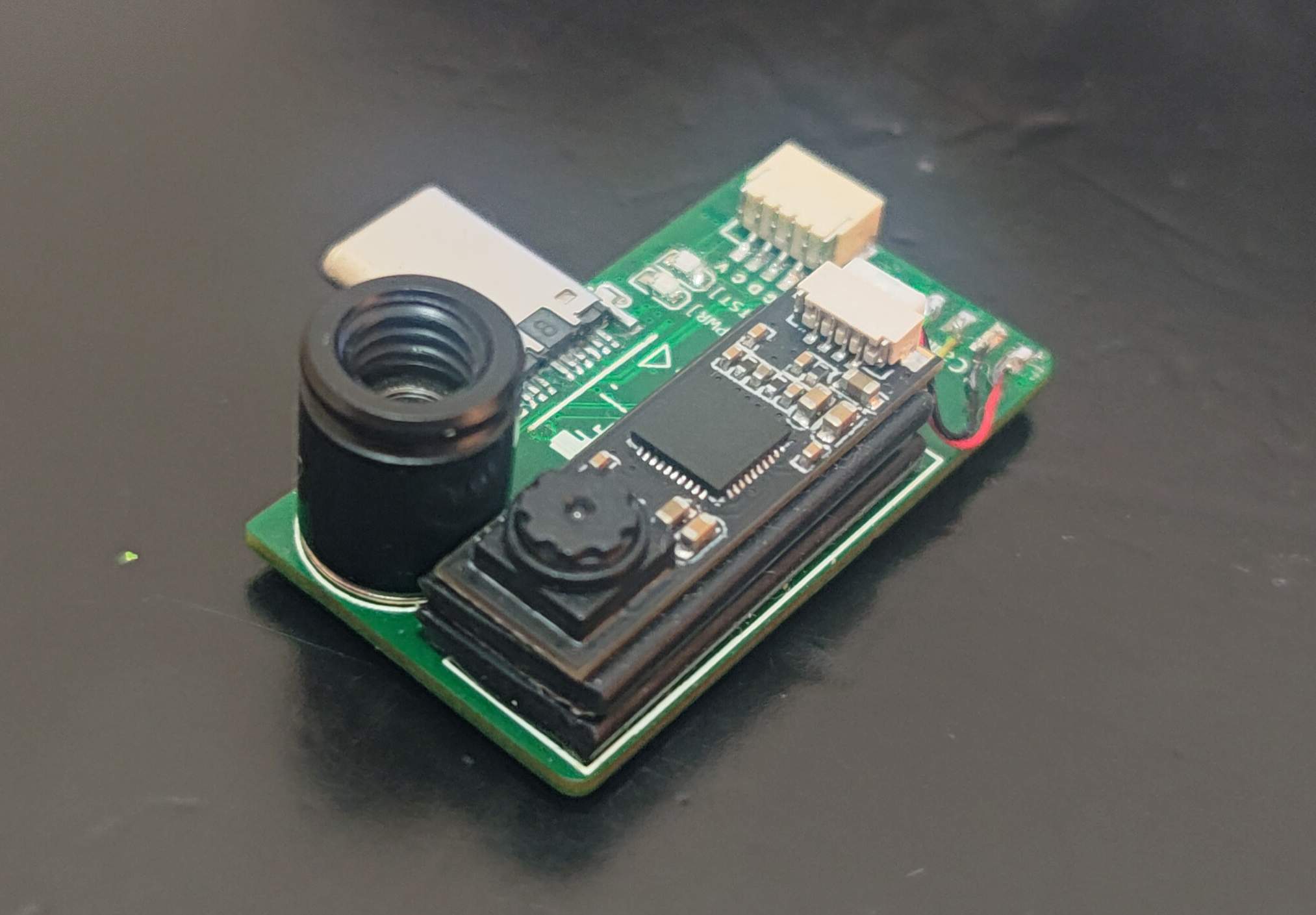
## Project Description The visible light camera has the characteristics of high resolution and high frame rate. The thermal imaging sensor can measure the temperature distribution, but the resolution is low and the frame rate is low. The visible light image is used to compensate the thermal imaging image, so that a higher quality heat distribution map can be obtained. The body has an ordinary visible light camera and a thermal imaging sensor. After being read by the MCU, it is transmitted to the mobile phone through the USB interface. It uses the powerful computing power of the mobile phone to perform image processing and fusion, and the final image is displayed on the mobile phone screen. ## Open Source Agreement Under the MIT Agreement, the licensee has the right to use, copy, modify, merge, publish, distribute, sublicense and sell the software and copies of the software. The licensee can modify the licensing terms to the appropriate content according to the needs of the program. The copyright statement and license statement must be included in the software and all copies of the software, but the original author does not bear the risks after use and has no obligation to provide technical support. ## Project Related Functions The overall functional framework of this project is as follows: MCU reads thermal imaging sensor data through I2C interface, and then transmits it to USB Hub through USB interface. Camera is a universal no-drive USB camera, which is also connected to the USB Hub and connected to the Android phone. There are two devices on the Android phone, one is the Camera, the other is the thermal imaging sensor. The data of the two sensors are obtained at the application layer of the Android phone, and the thermal imaging images with higher resolution and better quality are obtained through the fusion of certain algorithms. ![0bbeb99e6e164478a6a63b677a10c409.png](//image.lceda.cn/pullimage/FYLa2TquijLpb5e1ZUwbHl58ZVKBOO4N2wHzDYI6.png) ## Project Properties This project is made public for the first time and is my original project. The project has not won any awards in other competitions. ## Project Progress ### 20231128 The basic functions are OK, but the degree of completion still needs further optimization. The known issues are as follows: 1. The line connection from STM32 USB to SL2.1A is reversed and has been corrected in the project. 2. Scenes that are too bright will display images that are overexposed. 3. Screen rotation is currently not adapted, please turn off screen rotation. ### 20240203 1. Added functions of high and low temperature tracking, algorithm parameter adjustment, fusion mode switching, and frame rate switching. 2. Optimize the interface, fix some bugs, and automatically lock screen rotation. 3. Added 3D printed shell. ## Design Principles ### MCU The MCU uses STM32F411CEU6, with a floating point operation unit that can solve thermal imaging data, and USB FS. The minimum system circuit is as follows ![image.png](//image.lceda.cn/pullimage/qSTh6vAqOwVrG8lvIpAJrkquf6deNwQltHdNRQ6h.png) ### USB Hub The USB Hub uses SL2.1A and supports USB HS which can be used to transmit camera data. According to the manual, the crystal oscillator U3 is connected here and does not require welding. USB1 is a USB TypeC male connector, used to connect to mobile phones. ![image.png](//image.lceda.cn/pullimage/RJYE6QLzP9gJerl9D1OYCOI7q6COTYTrvrDUQi01.png) Camera uses a 640x480 [UVC camera daughter board](https://item.taobao.com/item.htm?id=567717780577&_u=3v1sub9e39d) , which is connected to CAM_DM/CAM_DP by welding. ### Thermal Imaging Sensor Thermal imaging sensor uses MLX90640, resolution 32x24 pixels, I2C interface maximum speed 1MHz. ![image.png](//image.lceda.cn/pullimage/OPnIjip8WAre75y81C3XrhbkPrvBATGRfDVdYVkf.png) ### Power Supply Directly use an LDO for voltage stabilization. The model is ME6211. This model can directly use low-ESR ceramic capacitors for input and output voltage stabilization. ![image.png](//image.lceda.cn/pullimage/hM31o5YQcMYDJd5oBWk7aMwQRdMI4kfgMeJnt4tg.png) ### Other LED Power light and test LED ![image.png](//image.lceda.cn/pullimage/eyVB7CdE3E7xiBLXBtey5GmXWRGlAkDsFBhcHFkf.png) Debugging SWD interface ![image.png](//image.lceda.cn/pullimage/nJBQ2bQdwftZrAC7HTZOvyvSO3OwybdmIl9outrk.png) Test point, the firmware uses UART2 as the Debug serial port ![image.png](//image.lceda.cn/pullimage/60QzBdg9U7E9cHs6BhsGsaSOKz14DnqcPwV0zFve.png) ## Software Description ### Code resources Divided into three parts: single board firmware, Android App and 3D printing shell. #### Board firmware **[https://github.com/colourfate/thermal_bridge](https://github.com/colourfate/thermal_bridge)** #### Android App **[https://github.com/colourfate/ThermalEyes](https://github.com/colourfate/ThermalEyes)** #### 3D printed shell **Please download the `3d_printed_casing.zip` file in the attachment, provide the step file, and the stl file can be printed directly.** ### Board firmware #### Development environment Currently using STM32CubeIDE. #### Software Process The software is divided into two parts: mlx90640 driver and thermal imaging data transmission protocol. In general, the software process is to read data from mlx90640 through I2C, then package it, and finally send it using USB. The whole process uses one cycle, in which mlx90640 The temperature measurement range is -40 to 300 degrees Celsius, and the conversion to an integer with two decimal places is -4000 to 30000, which can be covered with a 16-bit integer. ![20241008-111732.jpg](//image.easyeda.com/pullimage/D2ABqWP9wn3HlLubT6nLBvYBdOn7wrAAGP7AHSvg.jpeg) #### MLX90640 Driver The mlx90640 official driver has been provided. You only need to implement the corresponding I2C read and write operations to read sensor data through the API. #### Data protocol The data obtained from the sensor needs to be sent via USB. Since the temperature obtained is of float type, the actual required accuracy only requires two decimal places. Therefore, converting to an integer can save bandwidth. The mlx90640 temperature measurement range is -40 to 300 degrees Celsius. You can use 16-bit signed integers, and the communication protocol with the host computer is as follows: ``` ---------------------------------------------------------------------------- | header | type | length | data[0] | data[1] | ... | data[n] | ---------------------------------------------------------------------------- ``` - header: uint16_t, start code, fixed 0x8000 - type: uint16_t, indicating data type - length: uint16_t, indicating the length of the data packet and the number of subsequent data packets - data: uint8_t array, put the actual data #### USB send The USB library is automatically generated by CubeIDE, and you can directly call USBCDC to send data. ### Android APP There are two USB devices here, one is a USB serial port for transmitting thermal imaging data, and a USB camera is used for transmitting image data. The Android side mainly completes data reading, fusion and display functions. #### Software framework Data reading from Camera and thermal imaging sensors has corresponding library support. Both libraries use asynchronous callbacks to read data, so the double buffer cache mechanism is used here. Take Camera as an example: 1. Initialize a queue with a length of 2. When the callback occurs, apply for a new buffer, copy the YUV data to the buffer, and then put the buffer into the queue. 2. Start a thread to continuously read data from the queue for data fusion 3. If the thread reads too slowly and the callback finds that the queue is full, it will remove a buffer from the queue and discard it, and then put the new buffer into the queue. 4. If the callback never comes, the thread will find that the queue is empty and skip the next read again. 5. Because each callback will apply for a new buffer, there is no concurrency problem with the buffer. 6. Queue addition and deletion access the same data structure, and there are concurrency issues. You need to pay attention to locking during operation. As mentioned above, there are two queues, one stores YUV data and the other stores thermal imaging data. The two queues are accessed through a thread. When both queues have data, they are taken out for data fusion. To sum up, the overall software The process is as follows: ![20241008-112322.jpg](//image.easyeda.com/pullimage/aTNvREdBOT0z9uK60cs9ugWgZqvQZzqMoTcW9334.jpeg) #### Camera data reading and preview Android supports camera using [UVCAndroid](https://github.com/shiyinghan/UVCAndroid) , refer to the article:[https://blog.csdn.net/hanshiying007/article/details/124118486](https://blog.csdn.net/hanshiying007/article/details/124118486) This library is developed based on[saki4510t/UVCCamera](https://github.com/saki4510t/UVCCamera) and provides a simpler interface. For preview and data reading, refer to the CallbackDemo. You need to rewrite the ICameraHelper.StateCallbackd. Here you get the camera data and put it into the YUV queue in the format of NV21. #### Thermal imaging data reading and preview The thermal imaging data described in 3.2 is transmitted through USBCDC. What is seen on the Android side is a virtual serial port. In the Android development environment, [felHR85/UsbSerial](https://github.com/felHR85/UsbSerial) is used to provide operational support for the virtual serial port. The thermal imaging data is put into the queue in the callback. ### Data fusion #### Data acquisition Use a thread to obtain data. The camera frame rate is expected to be higher than the thermal imaging frame rate. Data fusion is performed only when the mYUVQueue queue has data. When the mThermalQueue has no data, the data of the previous frame is used. #### Fusion algorithm The camera here collects visible light images with a resolution of 640x480, and the thermal imaging collects temperature distribution with a resolution of 32x24. The purpose of the fusion algorithm is to make the temperature images collected by thermal imaging have more details by referring to visible light images. The first step of the fusion algorithm is to extract high-frequency information from the visible light camera. Currently, the Android APP integrates OpenCV. The previous method is no longer used. Here, the Gaussian blur method is used to extract high-frequency information. Refer to the blog: [Using OpenCV Mat to Image low-frequency information, high-frequency information extraction and lossless restoration \(Gaussian blur, difference, summation\)](https://blog.csdn.net/weixin_42727069/article/details/124858223) ```cpp Mat im_cam_l; GaussianBlur(im_cam, im_cam_l, Size(11, 11), 5, 5); Mat im_cam_h = im_cam - im_cam_l; ``` After extracting the high-frequency information, it is then superimposed with the interpolated and enlarged thermal imaging image to obtain the fused image, and finally the pseudo-color is given. ```cpp Mat im_fusion = im_cam_h + im_them_scale; applyColorMap(im_fusion, im_fusion_color, COLORMAP_JET); ``` The simulation effect is as follows. The first picture is a picture taken by the camera, and the second picture is a picture of the temperature distribution obtained by thermal imaging after interpolation and enlargement. The resolution is 640x480. ![cam_test.jpg](//image.lceda.cn/pullimage/QAH7NTrf7gtdx5TKHXrXewkutersBN52Hd8EHQjw.jpeg) ![therm_scale.jpg](//image.lceda.cn/pullimage/x5xMmgtG5QzWcPQeEDn8Z4ipwotCwTV7lmkQ5aQq.jpeg) First, high-frequency information is extracted from the visible light camera. The low-frequency information and high-frequency information are as follows: ![cam_l_test.jpg](//image.lceda.cn/pullimage/6StOLNcwavgzS001N1icVF6qUkbI07zppvkFmEob.jpeg) ![cam_h_test.jpg](//image.lceda.cn/pullimage/svw8DebX1YbYebojgwynjHKrkX8TNii2lVayxXoe.jpeg) Then superimpose the thermal imaging image and give pseudo color, using the JET color table, the results are as follows: ![fusion_test.jpg](//image.lceda.cn/pullimage/snCzImyvxVwDHGaXsNOXtRfLrrwHT0tbxDua4CzV.jpeg) #### Color mapping Color mapping directly assigns false colors to the thermal imaging image, and then superimposes it onto the visible light image in the YUV manner. Since the visible light image itself contains a large amount of information, it is equivalent to increasing the amount of information in the thermal imaging. The basic idea of ​​color mapping is to convert the RGB components of thermal imaging into YUV components according to the formula, and then subtract 128 from each as the offset of the visible light image, and superimpose it into the visible light image. The color mapping effect is as follows: ![color_map.png](//image.lceda.cn/pullimage/Zd7NsS4KS2Nb5J5GYzbeuvlEKts6Rck0KmK6HoCF.png) ## Design considerations 1. U3 magnetic beads are for testing only and do not require welding! No welding required! No welding required! 2. The USB cable from STM32 to SL2.1A is connected backwards. After using the flying cable to correct it, it is verified to be normal. It has been modified in the project, but the time is too tight and the proofing has not yet been done. If you are not worried, you can go back to the release_1 first proofing version in the version control. , and then correct it yourself ![8888.jpg](//image.easyeda.com/pullimage/RQQs7y1gsvLgmyPHWDp6M09uD0n7uyNBkLOHGAO4.jpeg) 3. The board sample thickness in the demonstration is 1.2mm. 4. The USB speed of the camera is relatively high, and impedance control is required during proofing. 5. For the camera daughter board, please refer to [this link](https://item.taobao.com/item.htm?id=567717780577&_u=3v1sub9e39d) . The distance between the connecting lines is 0.8mm. Please refer to [this link](https://item.taobao.com/item.htm?id=582653807364&_u=ov1sub99c01). ![20241009-094201.jpg](//image.easyeda.com/pullimage/MAMxJNuETzAHXdgBUsf0vwv9tl4LgFmPlquJ6FsT.jpeg) ![20241009-094303.jpg](//image.easyeda.com/pullimage/fH07S3PyD3YCIdTjQEctRa1vHAylcRtzgKduxLLN.jpeg) 6. The mlx90640 sensor is relatively high. It is best to raise the camera daughter board a little higher. ## Physical Display #### B station video The following is an earlier version. #### Demo **[https://www.bilibili.com/video/BV1M64y177ig](https://www.bilibili.com/video/BV1M64y177ig)** #### Principle explanation **[https://www.bilibili.com/video/BV1yb4y1T7hD](https://www.bilibili.com/video/BV1yb4y1T7hD)** #### Single board hardware ![P31122-195021(1).png](//image.lceda.cn/pullimage/O24gfE3lH58Pq7dpORrRRF8d5xLHIPx5jyXcKb8y.png) ![1706934410245(1).png](//image.lceda.cn/pullimage/6j2ZOelxkfbG4KRxo5oLGlHlUV9SrNymTJLWFf7a.png) #### Film effect ![IMG_0093(1).png](//image.lceda.cn/pullimage/nSoZMD4TI0IjX0yVpGMVFJYxdmw8eun8sVWO8pcn.png) #### Color mapping effect ![S40203-12200636_com.example.thermaleyes(1).png](//image.lceda.cn/pullimage/GLbC30iHUQe917s92LYsgYDCrev08k03rie3twmG.png) #### Image fusion effect ![S40203-12193689_com.example.thermaleyes(1).png](//image.lceda.cn/pullimage/1p5H9o6TYOGw7iz4Tk2rG7mC3cSx0JbOOsrRmS6J.png)

Designed by colourfate (from OSHWHub)

Link:https://oshwhub.com/colourfate/binocular_thermal_imager

Design Drawing

Design Drawing

schematic diagram
1 /
PCB
1 /
The preview image was not generated, please save it again in the editor.
Empty
Project Attachments

Project Attachments

Project Members

Project Members

Target complaint
Related Projects
Change a batch
Loading...

Comment

Add to album ×

Loading...

reminder ×

Do you need to add this project to the album?

服务时间

周一至周五 9:00~18:00
  • 0755 - 2382 4495
  • 153 6159 2675

服务时间

周一至周五 9:00~18:00
  • 立创EDA微信号

    easyeda

  • QQ交流群

    664186054

  • 立创EDA公众号

    lceda-cn