## Introduce
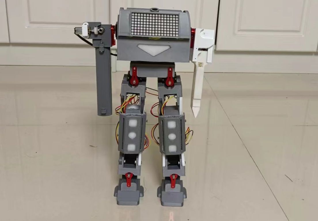
The combat robot completes the functions of the robot through the combination of various modules. The main control board (the brain of the robot) is the use of the Liangshan Pi development board, the main control chip of the development board is GD32F470, GD32F470 has a wealth of peripherals, and the main frequency is 240M. It may perfectly support the implementation of various functions of the robot. On the basis of the main control board, an expansion board is added to allow the main control board to communicate with each device of the expansion board. The following diagram is shown for the expansion board.
![扩展板实正面.jpg](//image.lceda.cn/pullimage/bDVC0KJF52NmFD2YCKZlC8HfCcEBvadEufxo5o5a.jpeg)
## Description of each functional module
The robot uses 7 modules and 7 drive circuits. The module uses stepper motor module, bus servo module, 0.96-inch OLED module, MAX7219 dot matrix screen module, HLK-V2.0 offline interlanguage module, WS2812 colored lamp, attitude sensor MPU6050, CAN bus circuit, digital triode drive circuit, 5V power supply circuit, buzzer drive circuit, ADC battery detection, 9G servo drive, and health detection. Commonly used modules will not be mentioned here, because the modules are all from the Liangshan Pi Transplantation Manual, and the program is also CV. Focus on the ones that are not in the manual or have major changes in the program.
1. Power supply
The power supply of the robot is the core, without enough power, the robot can not move, and the use of 25 WS2812 5050 electric color lights and dot matrix screens are very power-consuming, and the total current is expected to reach about 1A. I saw that the power chip of the SGM6132 of Shengbang Microelectronics used on the medicine delivery trolley of the electric race can reach up to 3A, and the voltage can also be adjusted. As shown in Fig.
![电源芯片.png](//image.lceda.cn/pullimage/tyZ57ICntxlmtLxpTiiJVW7uBclJ9xLCQKQpAvA2.png)
Each module is powered by a 5V power supply, directly through R1, R2, R3 and C3. Adjust the output supply voltage. The 3.3V is output through the Yangsan Pai development board. The power supply circuit is shown in the figure.
![电源电路.png](//image.lceda.cn/pullimage/eUHn3F6XWEiN1EFSADGuh1dekikNZLd5TMegZU61.png)
The battery uses two 18650 2000MA batteries, which are powered by a 16A switch. As shown in Fig.
![电源开关电路.png](//image.lceda.cn/pullimage/Jo0ciC8d6Wn4wKdfXzNnNSs9ITWcnFUzS8YQEK2O.png)
2. Bus servo
The main component of the robot is the aircraft, which uses UBTECH's UBTECH bus servo, which is a second-hand servo bought before, and if you use a new one, the bus servo is more expensive. 10 servos were used. Eight for leg joints and two for weapon lifting. This bus servo uses a half-duplex serial port for communication. Liangshan Pi can also be equipped with a serial port for half-duplex communication, but it has not been configured before, I don't know if it can be matched, and I will try to match it again when I have time. Now use the circuit that I have already tuned before, so that there are fewer detours and time savings. As shown in Fig.
![总线舵机电路图.png](//image.lceda.cn/pullimage/3I60u99oMyl6jcHzqGrGVccMenlXSO2KDL83Dr9E.png)
The information of this bus servo is directly placed in the file below. If you have a small partner in need, you can download it. It is important to say that this bus servo sends data from the sixteenth system through the serial port. I will explain the data structure, according to this data structure can be successfully controlled servo, you can also refer to my program. The reading angle was not realized, I don't know where the problem is, and I have time to study it again. The data structure is shown in the figure.
![舵机数据结构.png](//image.lceda.cn/pullimage/6cd3jWsOZ0dSYqtlpeUvcT4lVzlvJKogBBUjE36x.png)
The check bit is the sum of ID + instruction + data.
3. 0.96-inch OLED screen.
There is nothing special about the circuit of OLED screen. Guan Jian: I ported the U8G2 library of arduino to the Liangshan Pi. It is easy to call the functions of the U8G2 library. The software I2C driver is used. The U8G2 library data is used to display the logo and battery level of the Lckfb, which is demonstrated in the video. I wanted to make a cool menu, but I didn't have time to adjust the program, so I had time to add a single dish.
4. MAX7219 dot matrix screen module
The dot matrix screen uses only two 37*37 dot matrix, which mainly shows the robot's eye expression.
5. Offline voice module
The voice module is also the module of Hi-Link V2.0. This voice module is detailed in the video tutorial for smart curtains. The voice module is still very easy to use. Five commands were created on the speech module for testing purposes. The circuit diagram is shown in the figure.
![语音电路图.png](//image.lceda.cn/pullimage/W1Vm8GYO98KdS3yQ6vDri64NMS2XGYpQq7bGbgEV.png)
## Description of the robot structure
1. Description of servo distribution ID
![机器人ID号分布图.png](//image.lceda.cn/pullimage/y9HJLl3eMzMXLnIs1XBPYujyCLJnPwQO9xSiEpQl.png)
2. Each module of the robot is connected to the IO table
![各模块IO分布表.png](//image.lceda.cn/pullimage/S1mQJock000NRI8fFoxopiHcrdHwEvSkHnCET7lu.png)
3. Share pictures inside the robot
![内部图1.jpg](//image.lceda.cn/pullimage/3BrJejSZ50jHXAs3AmczEzvgnLIpAReWNnxGF8k6.jpeg)
![内部图2.jpg](//image.lceda.cn/pullimage/RjKdhF7kWtplLqhpXUzNaNRhXaThKuU5hGlISx9J.jpeg)
4. Description of the position of the device in the robot head
![头部器件1.jpg](//image.lceda.cn/pullimage/hZ41iJfLwA0CJ46a6XHAd8qKnIK4IOL9rd1wUTmy.jpeg)
![头部器件2.jpg](//image.lceda.cn/pullimage/02LBGGwSJddl9qxtGcJcSFfjCWqQN1oJZ5us46j1.jpeg)
5. The whole picture of the robot
![机器人图1.jpg](//image.lceda.cn/pullimage/dXuc2zEBaOVjXaxU71erz6Ng3zMNfabpvVf8YtOI.jpeg)
![机器人图2.jpg](//image.lceda.cn/pullimage/RDoyvjQZGfX4r2KnzRw7zxsqu9u9wMp6IhxaGsHC.jpeg)
## The video address of Bilibili
[Battle robot, master using the Liang Shan Pi development board.](https://www.bilibili.com/video/BV1VG41127Dq/?spm_id_from=333.999.0.0&vd_source=11a361314ce81edd5129af7fd3ef9b2c)
## Summary
The bus servo has many advantages in use, and the parallel use saves a lot of trouble for the line and uses less IO port. And the speed can be controlled. It took two months to complete the 3D modeling and debugging of each module, but the program did not have time to debug properly, and there was too little time left for debugging the program. The walking posture is still not adjusted, and it is not as good as imagined. There is time to update the program further.