 Completed
Based on MT7621 wireless router
PRO Based on MT7621 wireless router
License
:GPL 3.0
Description
Project Description
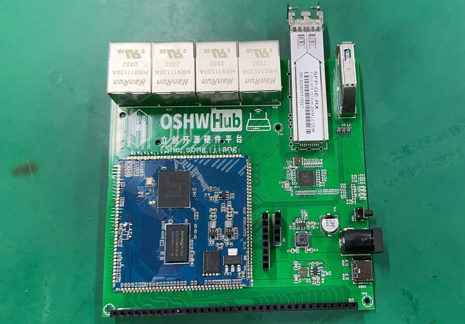
Hardware configuration:
- CPU: MT7621 chip
- 3 Gigabit LAN ports
- 1 Gigabit WAN port
- 1 USB port
- 1 SFP port
Software configuration:
- Openwrt open source system
Open source agreement:
GPL 3.0 As long as products under the GPL license are used in a project, the project must adopt the GPL license and must be open source and free.
Project Related Functions
It is a router hardware based on the MT7621 chip. It is equipped with 1 Gigabit LAN port and 1 Gigabit WAN port, 1 USB interface and an SFP interface. All these functions make it a high-performance, multi-functional for home or small office router use.
Main interface:

WiFi:
Project Properties
This project is made public for the first time and is my original project. The project has not won any awards in other competitions.
Project Progress
2023/10/12, the hardware has been completed and the software has been successfully started.
Design Principles
Hardware Description
1. Power supply part
The power interface has a DC head and a Type-C, using 2 DC-DC. Since we use the MT7621 module, we only need 2 power supplies, 12V to 5V, and 5V to 3.3V.
2. Interface part:
The DC port can directly input 9V-12. Type-C input voltage is 5V, just use any 5V charger, no protocol IC is added, reducing DC-DC losses along the way.

3.DC-DC circuit:
Use TPS563201DDCR to implement the BUCK circuit and convert to 5V and 3.3V. Note that the inductors used here are different between 3.3V and 5V. According to the manual, 3.3V requires 2.2uH, and 5V requires 3.3uH.

4.Reset circuit:
Directly connect a tact switch to the RST pin of the module. 
5.Network port circuit:
Use the RJ45 network port integrated with the transformer, and connect the double LEDs in parallel.

6.Mili-PCLE circuit
Uses standard Mili-PCLE interface. Connect to a set of PCLE and USB ports, and the LED indicator light is the wireless network card indicator light. When the wireless network card is connected and started normally, the indicator light will light up.
7.SPF interface circuit:
Use RTL8211FSI-VS-CG to implement SFP access to the network port. The RTL8211 interface rate supports up to 1000M. The I2C interface of SPF currently has no function. The purpose is to enable the software to directly implement the PON function in the future.


8.USB circuit:
Use standard USB3.0 interface and add magnetic beads to reduce interference. 
Software Description
## Notice
1. **Do not use root user to compile**
2. Domestic users should prepare magic before compiling.
3. Default login IP 192.168.1.1 password password
## Compilation command
1. First install the Linux system, Debian 11 or Ubuntu LTS is recommended
2. Install compilation dependencies
sudo apt update -y
sudo apt full-upgrade -y
sudo apt install -y ack antlr3 asciidoc autoconf automake autopoint binutils bison build-essential \
bzip2 ccache cmake cpio curl device-tree-compiler fastjar flex gawk gettext gcc-multilib g++-multilib \
git gperf haveged help2man intltool libc6-dev-i386 libelf-dev libglib2.0-dev libgmp3-dev libltdl-dev \
libmpc-dev libmpfr-dev libncurses5-dev libncursesw5-dev libreadline-dev libssl-dev libtool lrzsz \
mkisofs msmtp nano ninja-build p7zip p7zip-full patch pkgconf python2.7 python3 python3-pyelftools \
libpython3-dev qemu-utils rsync scons squashfs-tools subversion swig texinfo uglifyjs upx-ucl unzip \
vim wget xmlto xxd zlib1g-dev python3-setuptools
3. Download the source code, update feeds and select configuration
git clone https://github.com/coolsnowwolf/lede
cd lede
./scripts/feeds update -a
./scripts/feeds install -a
make menuconfig
4. Download the dl library and compile the firmware
(-j is followed by the number of threads. It is recommended to use single thread for the first compilation)
make download -j8
make V=s -j1
Second compilation:
cd lede
git pull
./scripts/feeds update -a
./scripts/feeds install -a
make defconfig
make download -j8
make V=s -j$(nproc)
If reconfiguration is required:
rm -rf ./tmp && rm -rf .config
make menuconfig
make V=s -j$(nproc)
Output path after compilation is completed: bin/targets
The configuration of menuconfig is used as shown in the figure:

Note: To use lede to compile, you need to find the AP-MT7621 model in the file in the path target/linux/ramips/image/mt7621.mk, and add $(Device/uimage-lzma-loader); you need to compile the wireless driver of MT7612E That’s it. When compiling the wireless driver, you need to add the WPAD software, otherwise the system can recognize the network card but not the SSID. Just select it and compile it directly.
Physical Display
Click on the text to view the demonstration video

Designed by She song jiang (from OSHWHub)
Link:https://oshwhub.com/ssj1322320585/ji-yu-MT7621you-xian-wang-guan
Design Drawing
 The preview image was not generated, please save it again in the editor.
 Empty
Empty


Comment