

 Completed
[Autonomous driving] Mini intelligent car Liguanxi-smart-car
PRO [Autonomous driving] Mini intelligent car Liguanxi-smart-car
License
:GPL 3.0
Description
Project Description
Ideas are born
In 2021, the big guy "稚晖君" of station B made a bicycle, and I saw that he used the ROS system, which can create 2D maps, plan paths, and recognize images.
There is also the aircraft of Fast-Lab of Zhejiang University, which also uses the ROS robot system to carry out various intelligent operations.
I originally thought that the ROS system was very complex and difficult to understand, but I didn't expect to find that after a little study, the ROS system is equivalent to a more difficult "Lego bricks", there will be big guys who will encapsulate the code into various "function packages" like Arduino "library", I don't need to write navigation algorithms or mapping algorithms, just go to the official website to download the corresponding version of the code package and then modify some of the parameters inside, These packages can then be connected to complete all sorts of seemingly tall operations such as mapping and navigation.
Of course, there is still a bit of a difference between the actual operation and the theory.
In order to practice, I wanted to buy a finished car and learn ROS, but I found that the price was too expensive...... If you want to complete the basic mapping function, the price will be thousands of yuan. Of course, in the end, I spent more than 2400 to buy one and studied for 1 month.
After completing the basic learning, I found that the car was basically useless and put aside to eat ashes, which was a little expensive to learn. I thought it would be like this, but I found out that the big guy "Yuxiang ROS" made a car that could run the ROS system remotely. Of course, the overall is a little bigger than mine, and the price is 600-700.
So, I did it again!
I wondered, can I repeat my 1 month of learning? Can I also make a low-cost and relatively small smart car?
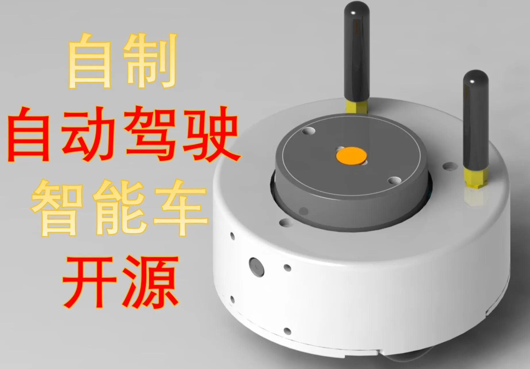
With this in mind, the project began. In the end, the size of the project is the size of a palm, the cost is controlled at about 260 yuan, and the appearance is more exquisite, so it must be shelled
Pictures of the finished product

Open-source protocol
GPL3.0
This is the General Public License of GUN, as long as the product under the GPL is used in the project, then the project must be licensed under the GPL, that is, it must be open source and free.
The starting point of the GPL is the open source and free use of the code and the open source and free use of the referenced, modified and derivative code, but it does not allow the modified and derived code to be distributed and sold as closed-source commercial software.
The most notable features of the GPL are "virality" and "no closed-source commercial distribution", and the Linux we are familiar with is licensed under the GPL.
Project-related features
Completion of major functions(7)
- Use the mobile app to manually control the movement of the trolley (completed)
Specific function: You can use two remote controls to independently control the front and back and left and right, so that the control effect is better, and some simple data can also be fed back.
- 2D mapping with LiDAR, display with RVIZ visualization tool (completed)
Specific functions: Manually control the trolley to move to explore unknown locations, use lidar to draw the surrounding outline, and draw a two-dimensional plane map.
- Navigation with LiDAR, display with RVIZ visualizer (completed)
Specific function: After running, the map drawn by the previous function will be opened, and any point will be marked in RVIZ, and the car will automatically plan the route and drive to the corresponding point, and the sudden obstacle will also automatically detour.
- Tracking a target using radar (completed)
Specific function: After running the function pack, it will automatically follow the nearest object, which is still relatively chicken, and can only be used in a relatively wide place, otherwise it is easy to follow.
- HSV patch tracking with camera (completed)
Specific function: This can only track the color block, the main function is to convert the image to HSV, the HSV value of each color is different, determine the color block area by finding the value, and then output the coordinates, and finally track according to the coordinates.
- Target Feature Recognition Using a Camera (Completed)
Using the find_object_2d function package, the screen will appear after running, as well as the generated feature points, and the corresponding objects can be selected, and you can identify them.
- Charging and discharging via USB (completed)
You can use the USB port to charge, otherwise it will be more troublesome to remove the battery
Partial Drop of Additional Functions(3)
- The mobile phone displays the mapping results and video screen (discarded)
Cause: The URL can only be read by one device at the same time, and multiple forwards will cause the picture to lag severely (no solution found)
- Simple obstacle avoidance (abandonment) with one's own computing power without using a computer
Reason: The newly compatible X2 radar data can not find the packet structure and cannot be intercepted, it is directly forwarded to the host computer after reading, which is more versatile, and one program can be compatible with a variety of radars without switching programs
- RRT Autonomous Exploration and Mapping (Abandoned)
Cause: Poor exploration (no workaround found)
Project properties
This project is the first public and is my original project.
The main frame of the chassis code is modified from the Liguanxi-UAV aircraft code, and the code style is the same as that of the previous project.
Most of the knowledge used in the project is obtained from the Internet, and most of it is open and free materials, which are linked below.
CSDN Forum
JoystickView: Android library for creating custom gamepads - CSDN Blog
CMOS Debugging Experience_ov2640 Driver Initialization Imaging Blur - CSDN Blog
ESP32 Arduino Learning (1).Setting Static IP_esp32 Static ip-CSDN Blog
ROS Publish & Subscribe to Images_ros Subscribe to Images - CSDN Blog
ESP32-CAM takes pictures and shows how _esp32cam take pictures in a web server - CSDN Blog
esp32cam camera + host computer opencv face recognition _opencv.js esp32-cam-csdn blog
Linux, socat is used to map serial ports to TCP server ports_socat Serial Ports-CSDN Blog
Convert RGB and HSL colors to and from _hsl rgb-CSDN blog
HSV color space table and the usage of cv2.inRange() _hsv range-CSDN blog
opencv tutorial CV2 module - image processing, HSV, hue, brightness adjustment_cv2 hsv-CSDN blog
DWA Parameter Tuning 2_dwa Parameters - CSDN Blog
Github
https://github.com/YDLIDAR/YDLidar-SDK/blob/master/doc/howto/how_to_build_and_install.md
https://github.com/rauwuckl/ros_simple_follower
GitHub - ros/solidworks_urdf_exporter: SolidWorks to URDF exporter
Bilibili video site
Robot Operating System ROS Quick Start Tutorial_Bilibili_bilibili
Book
《ROS Educational Robot Training Course》
《Linux from Beginner to Mastery 2nd Edition》
Project progress
The overall progress of the project, the application for the cost of project consumables is required!
January 15, 2024 - February 3 , 2024 The project is approved and the basic knowledge of ROS and network communication is supplemented.
Feb 4 , 2024 - Feb 8, 2024 Use SoliWorks to build a model and confirm the shape and part structure.
February 9 , 2024 - February 12, 2024 Create a virtual machine to build a compilation environment related to the ROS system.
February 12, 2024 - February 17, 2024 Build the basic prototype peripheral code of ESP32 code and mobile APP remote control (first version, using arduino code editor, lighting technology APP)
February 18, 2024 - February 18, 2024 Determine the specific component model, the specific implementation direction and establish the JLC project.
February 18, 2024 - February 23, 2024 The first version of the PCB circuit was completed.
February 23, 2024 - April 1, 2024 Work Reason: The project is suspended for a period of time.
April 1 , 2024 - April 4, 2024 Verify the feasibility of the communication UDP/TCP communication link, and the radar data can be observed using RVIZ.
April 5 , 2024 - April 7 , 2024 Overturn the first version of the PCB and backplane code design and redesign the second version.
April 8 , 2024 - April 11, 2024 Modified model to fit new chassis training wheels.
April 12, 2024 - April 20, 2024 Work Reason: The project is suspended for a period of time.
April 20, 2024 - April 22, 2024 Build the basic prototype peripheral code of ESP32 code and mobile APP remote control (second version, using ESPressif code editor, Write your own Android APP from the source code).
April 22, 2024 - April 24, 2024 Learn Android Studio to write a remote control APP program using java.
April 24, 2024 - May 1, 2024 Complete the second version of PCB, and make PCB and SMT (Jia Lichuang reimbursed 1047.48 yuan), SMT price is mostly not the price of the device.
May 1, 2024 - May 3, 2024 Model tweaks, add antennas and modify cameras
May 4, 2024 - May 5, 2024 The mapping test is successful.
May 5, 2024 - May 12, 2024 Work Reason: The project will be suspended for a period of time.
May 13, 2024 - May 18, 2024 PCB arrival test basic code, chassis part for sensor reading and conversion, circuit check.
May 18, 2024 - May 22, 2024 The PCB function is abnormal, the antenna circuit cannot be used, supplement the knowledge of RF circuit and the high-speed circuit design specification to redesign the third version of the PCB and make proofs.
May 23, 2024 - May 25, 2024 When waiting for a new PCB, the ROS system and the chassis system are jointly debugged to solve several problems such as automatic reconnection and abnormal data transmission.
May 26, 2024 - May 26, 2024 The third version of the PCB arrives for soldering and debugging.
May 26, 2024 - May 28, 2024 Mapping operation, but the connection is still unstable, the WiFi signal is relatively poor, the preliminary judgment is that the filter circuit is not well configured, learn relevant knowledge to acquire the network vector analyzer, ready to adjust.
May 28, 2024 - June 1, 2024 During the drawing process, it was found that two auxiliary wheels would cause the trolley to swing with the rotation of the radar, and the structure was not very reasonable.
June 2, 2024 - June 2, 2024 Since the network vector analyzer has not yet arrived, it is much better to perform a simple calculation and use the universal matching signal, perform a complete mapping, and save it.
June 3, 2024 - June 3, 2024 Improve open source documentation.
June 4, 2024 - June 5 , 2024 Use the vector network analyzer with SmithV4.1 to adjust the antenna circuit parameters, and finally control the VSWR within ±1.3 to modify the WiFi channel.
June 5, 2024 - June 6, 2024 Optimize the PCB layout, learn the corresponding routing rules, and try to comply with the specifications.
June 6 , 2024 - June 7, 2024 All TCP communication is switched, and the positioning parameters are modified, and the positioning effect is significantly improved.
June 8, 2024 - June 8 , 2024 Make BOM lists, communication link diagrams, and improve some open source projects.
June 9, 2024 - June 10, 2024 Debugging navigation functions, constantly adjusting the parameters of the cost map and the trolley, assembling a new car body, and shooting a demonstration video
June 11, 2024 - June 15, 2024 PCB arrival soldering verification.
June 16 , 2024 - June 17, 2024 Optimize the chassis of the trolley to add a closed loop of motion, and debug the anonymous host computer.
June 18 , 2024 - June 18 , 2024 Improve open source documentation.
June 19 , 2024 - June 25, 2024 Verify the camera solution and use ESP32S3CAM to verify the communication link with ROS.
June 25 , 2024 - June 30, 2024 Draw the first version of the camera circuit and PCB for proofing.
July 1, 2024 - July 5, 2024 Work Reason: The project will be suspended for a period of time.
July 6 , 2024 - July 7, 2024 The camera PCB arrived, and the soldering debugging was carried out to realize the basic object feature recognition and detection.
July 7 , 2024 - July 8, 2024 The high-speed line part is drawn with a problem, and the high-speed line is too close to the coupling, resulting in a picture freeze, flashing purple or green interference line, after supplementing the relevant knowledge, redraw the high-speed line part, increase the GND shield, open the distance between the high-speed lines, shorten the length as much as possible, and sandwich a GND line in the middle.
July 13 , 2024 - July 14, 2024 The second version of the camera PCB arrives and is soldered, and the effect is not bad, and the VGA can reach about 15 frames, and the naked eye observation is quite smooth.
July 14, 2024 - July 18, 2024 When adding the function package of radar tracking and visual tracking, it was found that there were some problems with the odometer, which was not very accurate, and it was not very accurate when controlling the chassis, because the fixed PWM conversion was used, the speed would be different according to the battery voltage, and the car could not go in a straight line, so PID control was introduced to correct the odometer and IMU.
July 19 , 2024 - July 22, 2024 Modify the calibration odometer, change the speed of the two wheels of the trolley to PID control, set the PID parameters, and optimize the operation process.
July 22 , 2024 - July 23, 2024 Debugging radar tracking, because the long-range radar data is not very stable, the tracking effect is not ideal, the visual data is also unstable, ping the IP address found that the delay is very high, adjusting the network connection relying on the router for connection delay is higher, can only change back to the original connection.
July 24 , 2024 - July 24, 2024 Compatible with X2 radar, I found that the data refresh rate has become faster but more unstable, the wall is distorted when rotating, but it is barely usable, and the LD14 refresh is slow but relatively stable.
July 25 , 2024 - July 25, 2024 Modify the shell to re-proof, modify the code to make it slightly tidy, and then jointly debug the vision module.
July 26, 2024 - August 4, 2024 Work reason: The project is suspended for a period of time.
August 5 , 2024 - August 6, 2024 When the radar is following, the front is always the radar junction point, 0-6.28 runout causes the tracking to be untrackable, adjust the TF tree, correct the radar direction, view the internal code of the following function package, modify the motion control part to achieve basic radar following.
August 6 , 2024 - August 7, 2024 In the following function package, the visual following function is too complex to understand, and I plan to write a function package by myself to supplement visual knowledge, detect a specific range of HSV, draw a color range and then output coordinates, and bind to the chassis speed to achieve basic color block tracking.
August 8 , 2024 - August 25, 2024 Supplementary learning of ROS cost map and path planning principles, adjustment of motion parameters and navigation parameters.
August 8 , 2024 - August 24, 2024 Supplement the knowledge related to video shooting, write copy, shoot videos, and edit videos.
August 24 , 2024 - August 26, 2024 Improve open source documentation.
Hardware design principles
First of all, I declare that I am still knowledgeable, aiming to learn the corresponding knowledge in the production, the first time to design a more dense circuit, if there is anything inappropriate, you can point it out in the comment area.
Main control chip part

Generally speaking, the robot system ROS needs to run on a microcomputer such as a Raspberry Pi, and I want to complete this project at the lowest cost, so I will run the ROS system computer from the onboard to the host computer, through WiFi and connect to the trolley, so that I can save a microcomputer.
But! The data of the radar is sent once in about 1ms, and a piece of ESP32 is obviously not enough! So, I chose to use two ESP32s as the main controller.
- A piece is dedicated to relaying radar data.
- The other piece is used for motion control and reads sensor data.
Similar structure Yuxiang ROS has been produced, but the body size is relatively large, and the circuit integration is low.
Antenna section
The ESP32 antenna part is more elaborate and involves high-speed lines.
The first is impedance matching, according to Espressif's hardware design guidelines, the RF part needs to be matched with 50R impedance.

|
|
In addition, Espressif Systems also gave a schematic diagram of the PCB stack, which I was still a little confused about, and I used JLC's impedance calculator to calculate what thickness of copper foil and how wide the line corresponded to this impedance. Finally, JLC04161H-7628 was used. 4-layer board,PCB thickness: 1.6, trace width: 32.2mil
|


 |
Device placement and routing planning. Then there is the placement and routing of the devices, which are also examples in Espressif's hardware design guide. |
The use of four-layer boards, top ornaments, can go to the top of the line is basically the top layer.

|
Inner layer 1 is fully copper-poured, ensuring a complete ground level.
|
Inner layer 2 takes some signal lines.
|


The bottom layer takes the power supply, because the thickness of the copper foil on the bottom layer is 1oz, and the thickness of the copper foil on the inner layer 2 is only 0.5oz, if the width of the bottom layer is doubled compared with the trace of the inner layer 2.

3D drawing

Antenna parameter tuning
However, the π-shaped circuit parameters at the antenna need to be adjusted according to the actual design, so the network vector analyzer is used for test adjustment.
First, the chip is removed, the test wire is soldered to the antenna pin, and the initial parameters of the π filter circuit are connected to a 0R resistor.

 |
The other end is connected to the vector network analyzer, the scanning start frequency is set to 2.4Ghz, the end frequency is 2.5Ghz, adjust the cursor to 2.412Ghz, because the trolley AP mode uses WiFi for channel 1 to correspond to the frequency of 2.412Ghz. |
After adjustment, as shown in the figure below, the performance of the antenna at the specified frequency is shown, the VSWR is 1.838, the Smith value is 79.26 + j25.63Ω, and the antenna performance is best when the VSWR is 1.0.

Open  |
|
 Enter the
 After confirming the input, the corresponding point is displayed, which basically corresponds to the measurement on the instrument, which shows a simplified version of the Smith circle, with the center of the large circle corresponding to the 50Ω impedance, and the small circle on the left omitted by the vector analyzer.

Add capacitors or inductors in series or parallel via the toolbar in the upper right corner to bring the measured point as close to the center as possible, each connection method will have different characteristics.

Finally, a capacitor of 1.5pf in series is calculated, and an inductor of 10.6nH in parallel at the antenna side can achieve the best antenna performance.

The software calculations are not completely accurate, and the actual connection needs to be slightly adjusted, first replacing the 0Ω resistor with a 1.5PF Smith value is almost centered, and there is no need for series inductance, and finally the 2.7PF series is tested for the best effect.

The antenna debugging is completed, remove the antenna and install the chip.
 |
There is also a high-speed circuit in the crystal oscillator part, which needs to be surrounded by GND as a shielding layer, and the wiring also adopts arc corners. |
The battery is designed to be non-removable, so a charging circuit is added, using TP4056 charging chip, check the manual, draw the circuit according to the manual, the charging current is set to 400ma, and the charging current is adjusted according to the resistance of the R21 resistor.
 |
 |
 |
 |
A switch is used at the battery interface to control whether the battery is charged, and there is a current detection circuit for detecting the battery discharge and charging voltage. The current is detected by the R14 resistance, according to Ohm's law I=U/R, that is, the current passes through the resistance, and the voltage difference between the two ends of the resistance will be generated, and the voltage difference divided by the R14 resistance is equal to the current passing through the resistance, and the voltage difference between the two ends of the resistance is relatively small, so an operational amplifier is used to amplify the voltage and then test it to the microcontroller. |
|
The power supply is first boosted to 5V and then regulated to 3.3V, which is used by microcontrollers and sensors.
|
The download part uses CH342F, the chip has two ports, you can use a USB to download two microcontrollers at the same time, and considering that the space is relatively compact, the DMMT3904 is used to replace the transistor of two NPN.
|


|
The sensor usage MPU6050 for IMU data.
|
The motor is driven by a DRV8833 with two N20 motors.
|


Lidar, using LD14, is mainly cheap, Taobao or salted fish buy and disassemble LD14 radar 25-60 yuan (new to about 250) but the number of second-hand is relatively small,
Also compatible with ydlidar X2 radar The radar of this protocol is more second-hand, ranging from 30-55 yuan, not only ydlidar's radar, but also the radar of other small factories can also be used, ask the store if it is compatible with the EAI protocol before buying, the 2 on the left of the figure below are EAI and the right is LD14, the hole position is almost the same.
 |
 |
|
The voltage measurement circuit measures the battery voltage and uses the resistor voltage division to the ADC port.
|
Buzzer, intended to do no power alarm, or some other sound such as boot tone.
|
Reserved for the camera board.
|


Camera section
The wiring of the camera still needs to be paid attention to, a GND line needs to be clamped between the high-speed lines of the antenna, and the high-speed lines should be kept as far away as possible, and the wiring should minimize the corners, otherwise the image of the camera will be interfered with in the end.
|
Top floor
|
Inner layer 1
|


|
Inner layer 2
|
under layer
|


3D drawing

In fact, this camera board can be done with 2 layers, but the high-speed line needs complete ground shielding, and the impedance of the antenna needs to be matched, if it is replaced with a 2-layer board, the wiring width of the antenna needs to be 100mil, which is outrageous, so in the end 4 layers of the board are used.
circuit
The main control chip adopts ESP32S3, and the antenna is SMD and ceramic antenna.

The camera adopts OV2640.

The download circuit is CH343P.

The power supply scheme refers to the chassis PCB, which is first boosted to 5V and then stepped down to 3.3V for use.

Then the voltage is stabilized to 1.2V, 2.8V, and 3.3V respectively to supply power to the camera and chip.

Software Description
Compile environment
ESP32 uses espressif-IED version 2.6.0 to edit and compile code.

|
Virtual machines are created using VM software.
|
The virtual machine system uses Ubuntu 20.04.
|


|
The ROS system uses the ROS1 Noetic version. noetic/Installation/Ubuntu - The ROS Wiki site can be found on how to install it.
|
However, the official website installation is more cumbersome, you can use the Yuxiang ROS one-click installation tool, which is very easy to use (praise the big guy). Input command : wget http://fishros.com/install -O fishros && . fishros After entering the command, just click the number and go down step by step to install it.
|


ROS function
ROS system uses noetic version,Or use ROS1,This structure is not the first one I use,Yuxiang ROS and other bigwigs have long been in use,The more mature solution is to run the ROS2 library on ESP32 so that you can publish the topic directly on ESP32,But I will only have a little ROS1 skin,It's still more difficult to learn ROS2,So I used TCP to transfer the serial port to be compatible with the original package, In this way, the function can be completed with a simple operation.
The positioning algorithm uses robot_pose_ekf and only uses odometers and lidar for positioning.

The mapping algorithm uses the karto mapping algorithm, and the parameters are default.

Navigation uses Navigation architecture, which is simply understood as this framework is provided by amcl adaptive Monte Carlo positioning function package, map-server publishes the map data of mapping, and then carries out path planning according to the target positioning released by rviz, outputs path and chassis movement data to control the car to reach the target point.
 |
 |
The chassis is connected to the computer through WIFI, and the specific communication link is shown in the figure below. |
The communication delay is still considerable, from top to bottom are the chassis, radar, and camera test using the computer's own network card, the car is about 20 meters away from the computer, there is a chair and a table in the middle, completely blocking the line of sight test delay results.
|

The specific file functions and structure of the ROS workspace.

Radar communication link, radar forwarding using TCP to send to the ROS host computer, and then by socat to create a virtual serial port for TCP and serial port transfer, and finally the serial port input into the radar function package, according to the radar you use to choose, you can choose LD14 or X2 function package.
Mapping effects


The motion control board communication adopts TCP to connect with the ROS host computer, and then the virtual serial port is created by socat for the transfer of TCP and serial port, and finally the serial port is output to the node of the chassis, and the TF and odometer are output after processing, and the value of the received cmd_vel is sent back to the chassis to control the movement.

Navigation effects

Map
There are 3 layers of the map, the first layer of the original map (the black one is covered by the color, and the already created map is imported)
The second layer of the global cost map is aligned with the principle map.
The third layer is a local cost map with a length and width of 1.5m around the body.
Meaning of color:
Pink corresponds to the original map, indicating that the area is an obstacle.
The light blue color is extended according to the radius of the body, for example, the radius of the body is 0.05 meters, and the width of this light blue area is 0.05 meters.
Dark blue is set according to the planning strategy, if you don't set this layer of the car will be along the light blue area planning path, if the driving route deviates a little will collide, after setting this area, the car planning route will try not to enter the area, note that it is not that you can not enter the dark blue area, but try to avoid it when planning the path, if you encounter two dark blueIf the regions overlap, they will try to rely on intermediate planning.
Monte Carlo positioning
The red arrow is the Monte Carlo positioning particles, the principle of Monte Carlo positioning is first, release a large number of particles, each particle as a possible position of a trolley, and then the trolley movement is constantly judging which particle is more consistent with the current sensor judgment, and then constantly remove the deviation that is too large, and then re-release the deviation is smaller, and finally the Monte Carlo particles will gather near the real position of the car.
Path planning
The global planning path generates a path based on the set coordinate points, according to which the obstacles known at the time of mapping can be avoided (green).
Locally plan the path, plan a local path to bypass the obstacle when you encounter an obstacle on the global planning path, and re-plan the global path if you can't avoid it (red).
DWA is used for local planning.
Extras for small features
 |
Radar tracking You can also make a simple follower. Using the radar tracking in the tracking package, it will follow the nearest object when activated, and will identify and track as long as it is close. |
 |
Visual feature recognition You can do object feature recognition, detect multiple features on the object, and then select the object to be recognized, and then match the feature points to identify complex objects. |
 |
Visual patch tracking
You can also detect the HSV value, detect the color block and track it, this is relatively simple, set the upper and lower limits of HSV, detect the value in a picture that meets this range, and then select the marking box to output a coordinate and bind it to the chassis speed to follow the color block. |
Mobile APP
The mobile phone APP and the chassis-driven esp32 do UDP communication, originally planned a lot of things, but the use of its own computing power to avoid the obstacle function was abandoned, and the image transmission function could not be realized, so the APP is basically a tabula rasa that can only control the movement of the car, and it should also be the knowledge reserve of the later project.
 |
 |
Iterative version image
 |
The verification machine is built with a direct flying line from the development board to verify the basic code.
Print a basic chassis and then use the hole board and module to fly the leads, this step is mainly to verify that the following circuits can be used, and then write out the program for the motor part, as well as the basic programs such as WiFi link and radar communication. |
The first version, the use of the inner antenna is relatively neat as a whole, there is no expansion module, and the effect is only usable, and the navigation is not stable.
 |
 |
The second version of the model adds an external antenna and a new camera with a lens.
 |
 |
The third version of the model, modify the camera for the SMD type, the cost of using a large lens is higher and not beautiful, the wheel is changed to a 3-point type, although it is not centered, so that OCD is really uncomfortable but can adapt to most of the ground, and finally it is mainly practical, the battery sinks into the chassis, freeing up a large space for the camera and line, and the PCB area can also be increased.
 |
 |
 |
 |
BOM


Finally, there is the cost
Statistics out of the BOM list, the budget has exceeded the total price of 307 yuan, the above price is in the case of the maker does not have any resistance capacitor reserves, need to buy all over again, the production will be left a large number of resistance capacitors, roughly estimated after the completion of the production will be left about 2600 resistance capacitors, screw parts, cables and various mechanical parts of the hundreds, more than a dozen chips.
If the maker has done other projects before, there are resistors and capacitors in reserve, and the finished product will be reduced to 240 yuan.
Open source materials
After the data is sorted out, it is put into the QQ group in the exchange group 263879824 Some data is far larger than 50M, so it cannot be placed in the attachment, and the information of the QQ group will be updated in real time.

Precautions when forking
1. The circuit is relatively dense, and the maker needs to have a certain soldering skill and the ability to judge the circuit failure, at least a basic electric soldering iron and heating plate, which does not need to be too expensive for dozens of dollars.
2. There are a lot of tutorials on the environment construction network, so I won't repeat it too much here, just build and import the function package according to the above environment version to use, but you must pay attention to the version, there will be various strange errors in different versions.
3. There are many devices, and the link may be partially invalid, so the maker needs to have a certain device retrieval ability, and search for devices according to the model to supplement the purchase.
4. Note: Although it is a weak current circuit, there are risks associated with improper use of batteries and various soldering tools, and users need to bear their own risks.
Other
If you think this project is not bad, you can like + collect it to support it.
The video of the complete design process will be sent to Bilibili, and all the materials in the JLC community are limited to 50M in size
Design process video:https://www.bilibili.com/video/BV1WZspefERu/
Reproduction tutorial video:https://www.bilibili.com/video/BV1MtsdebEQE/
Demo video: Upload attachments to demo videos, attachments can only be long-distance transmission of 50M files, files larger than 50M can be placed on other network disks or video websites, just put the address link here.
Project attachments: The works participating in the activity must upload the project-related program attachments to the open source platform or personal code storage cloud, and the attachments can be uploaded up to 50M (please do not upload them in the LC workspace, there are restrictions)
Designed by liguanxi (from OSHWHub)
Design Drawing
 Empty
Empty
Comment