Editor Version ×
recommended

Pro Edition

free

Brand new interactions and interfaces

Smooth support for design sizes of over 3W

devices or 10W pads

More rigorous design constraints, more

standardized processes

For enterprises, more professional users

Std Edition

Easy to use and quick to get started

The process supports design scales of 300

devices or 1000 pads

Supports simple circuit simulation

For students, teachers, creators

Completed

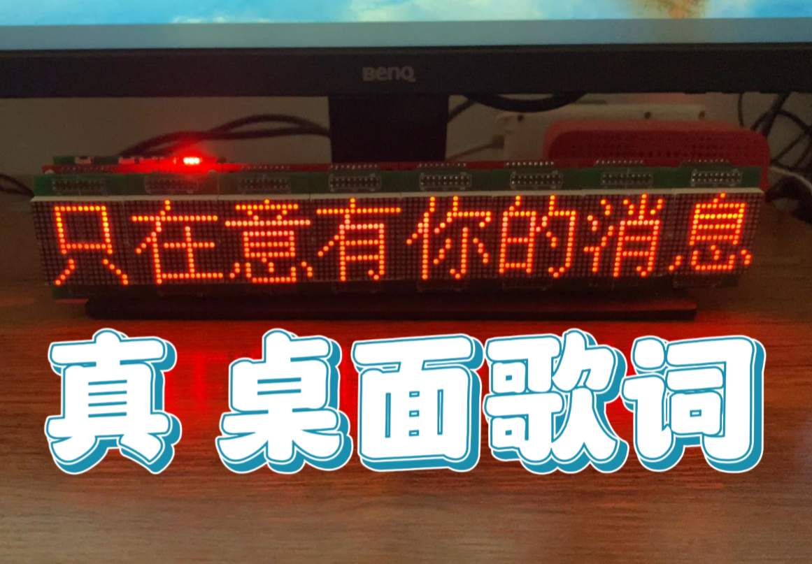
PRO MakerLab A multifunctional LED dot matrix screen based on ESP32 can display lyrics

A multifunctional LED dot matrix screen based on ESP32 can display lyrics

Project tags

License

GPL 3.0

License: GPL 3.0

Mode:

Mode

Editors' pick

Editors' pick

  • 121
  • 0
  • 0
Update time: 2024-11-13 09:13:29
Creation time: 2024-11-13 02:08:04
Description

Description

The dot matrix screen is composed of three parts: ESP32 control board, base board and module board. The module board needs to be inserted into the base plate, and then the base plate and the base plate are welded using headers to cascade. The difficulty of the project is on the Android APP. For a person who can’t write interfaces, I want to make the interface more beautiful. It takes too much time. The interface has been changed again and again. It has not achieved the effect I am satisfied with, so I have to make do with it. Please see the full effect demonstration here: [https://www.bilibili.com/video/BV1dX4y1R7UC/](https://www.bilibili.com/video/BV1dX4y1R7UC/) Open source GitHub address: [https://github.com/literem/led-matrix/](https://github.com/literem/led-matrix/) Once you enter the project source code, you can see the link. ### Hardware physical picture The effect of cascading eight 16x16 dot matrix modules: ![image-20230331143825363.jpg](//image.lceda.cn/pullimage/SBLrq46hKEAzm2gRZDNmR7gRgsiI2lBb2FFraNg8.jpeg) ![image-20230331143912285.jpg](//image.lceda.cn/pullimage/p9voEKNExBoMN4u9qd8SRqU2a2ZjMGkLMUN4tsIO.jpeg) No cascading effect: ![image-20230331144303057.jpg](//image.lceda.cn/pullimage/KQnjpQot5Q6zrcVF0xAh4Uq4bL828KpewNZSMwqG.jpeg) ![image-20230331144332983.jpg](//image.lceda.cn/pullimage/Apq3DZNqwsYMjWel1om4Cp7TM1rzZfjuJinXX2Lz.jpeg) ![image-20230331152305017.jpg](//image.lceda.cn/pullimage/NbCEHLmFZTDyCL5gmHtN6Mo8zQUqOk2NfgpVv6on.jpeg) ### Dot matrix control panel Using ESP32-WROOM-32E microcontroller, the GBK font used for dot matrix screens is placed inside, saving the trouble of external font chips. It supports battery power supply and external TypeC or DC interface input, and there is also a DC interface for charging the battery. The reason why the external power supply and charging interface should be separated is to avoid charging the battery all the time when the external power supply is used. Of course, you can also add a mos switch to control whether to charge, but this requires battery voltage acquisition and mos control circuits, as well as logical judgment of the code. , it was quite troublesome, so we simply separated. The chip on the right side of ESP32 is AT24C32, which is an E2PROM that stores dot matrix screen information. There is also a clock chip RX8025, which can be easily purchased from a certain store for more than one yuan. Next to the TypeC port is the CH340C chip, which downloads code for the ESP32. There are four buttons on the top, the one on the left is reset, and the other three buttons have not been developed for function and are just decorations at the moment. ![image-20230331152303041.jpg](//image.lceda.cn/pullimage/teB8GVnGzgUkVTh0qK0rQx9y1XFAdjFgILTpEueT.jpeg) ### Dot matrix base When welding the base plate, we use a 2.54mm 2x9P patch header. When welding, insert it into the dot matrix module first, align it with the base plate, then weld the outer contacts, and then pull out the dot matrix module and solder the inner contacts. point. ![image-20230331144616896.jpg](//image.lceda.cn/pullimage/Ffb2sGDIIizvDcGQaLFwWKTCHGleXxf14XiV9wZs.jpeg) ### Dot matrix module board ![image-20230331145701296.jpg](//image.lceda.cn/pullimage/o5ndx8rO8WAcXM0yl4rxGbblvEfNyt8B8NgFur2m.jpeg) ### Control software interface Connect device interface ![image-20230331151815400.png](//image.lceda.cn/pullimage/RDYwXnQxzDrfwm5eb2a8bckGugvXh8FCIltbhUqs.png) Functional interface ![image-20230331151836870.png](//image.lceda.cn/pullimage/lkD2AU15f7ZIDszZs0b87nhROvzpsUkRJ64mxpkm.png)

Designed by literem (from OSHWHub)

Link:https://oshwhub.com/cyaroge/dz_16-n_control

Design Drawing

Design Drawing

schematic diagram
1 /
PCB
1 /
The preview image was not generated, please save it again in the editor.
Empty
Project Attachments

Project Attachments

Order File name Download times
1

Demo video.mp4

411
2

Hardware display.mp4

521
Project Members

Project Members

Target complaint
Related Projects
Change a batch
Loading...

Comment

Add to album ×

Loading...

reminder ×

Do you need to add this project to the album?

服务时间

周一至周五 9:00~18:00
  • 0755 - 2382 4495
  • 153 6159 2675

服务时间

周一至周五 9:00~18:00
  • 立创EDA微信号

    easyeda

  • QQ交流群

    664186054

  • 立创EDA公众号

    lceda-cn