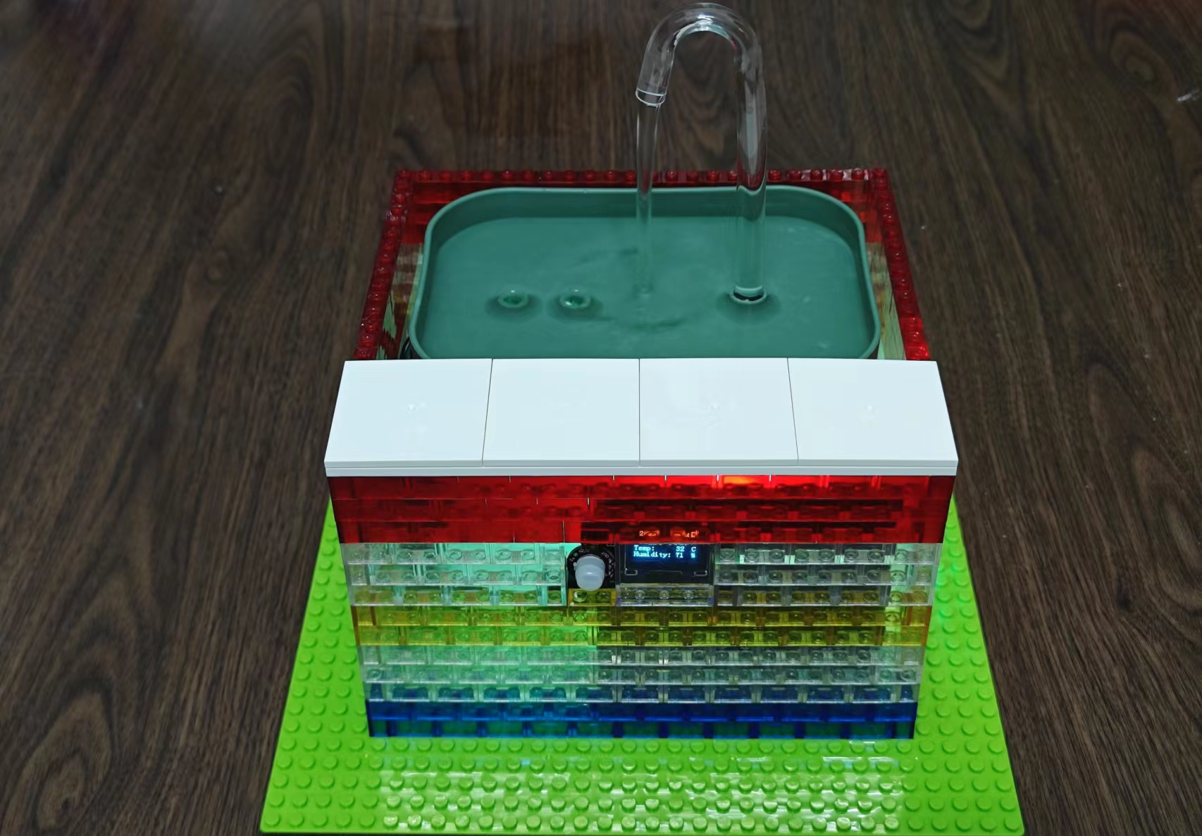
 Completed
# 8th LC Electric racing # Renesas RA-Cat Smart Water Dispenser
PRO # 8th LC Electric racing # Renesas RA-Cat Smart Water Dispenser
License
:Public Domain
Description
Introduction to project features
1. Automatically receive time through WIFI when powered on. (Video uploaded)
2. Alarm clock once per hour, turn on the water pump to change the water and control the opening time according to the temperature (whether it is greater than 30 degrees), 30s, 60s. (The alarm clock is turned on at 0 minutes every hour, and the video will not be recorded if it is tuned)
3. When a cat is detected, the pump will automatically turn on for a period of time. (Video uploaded)
4. Customize colorful RGB. (Video uploaded)
5. Detect whether there is water in the sink, if there is a lack of water, the buzzer will alarm and turn off the RGB light. (Video uploaded)
6. Detect the battery voltage, if the battery is low, the buzzer will send out an intermittent alarm and turn off the RGB light. (The effect is similar to the lack of water, but the alarm sound is different, and it is a bit difficult to wait for the battery to run out, so I won't record it)
7. It can be powered by battery, or it can be powered by TYPE-C (it can also charge the battery). (Image uploaded)
8. On-board serial port debugging interface, can also be debugged by SWD. (Image uploaded)
9.WiFi control water pump on.
10. The touch button can be extended to turn on the water pump.
(4 videos uploaded)
As we all know, cats always don't like to drink the water in their own bowls, so they want to make a smart water dispenser for their cats. A search on Taobao found that the price of smart cat water dispensers was generally too high, so I wanted to make one myself.

Project structure

Physical appearance
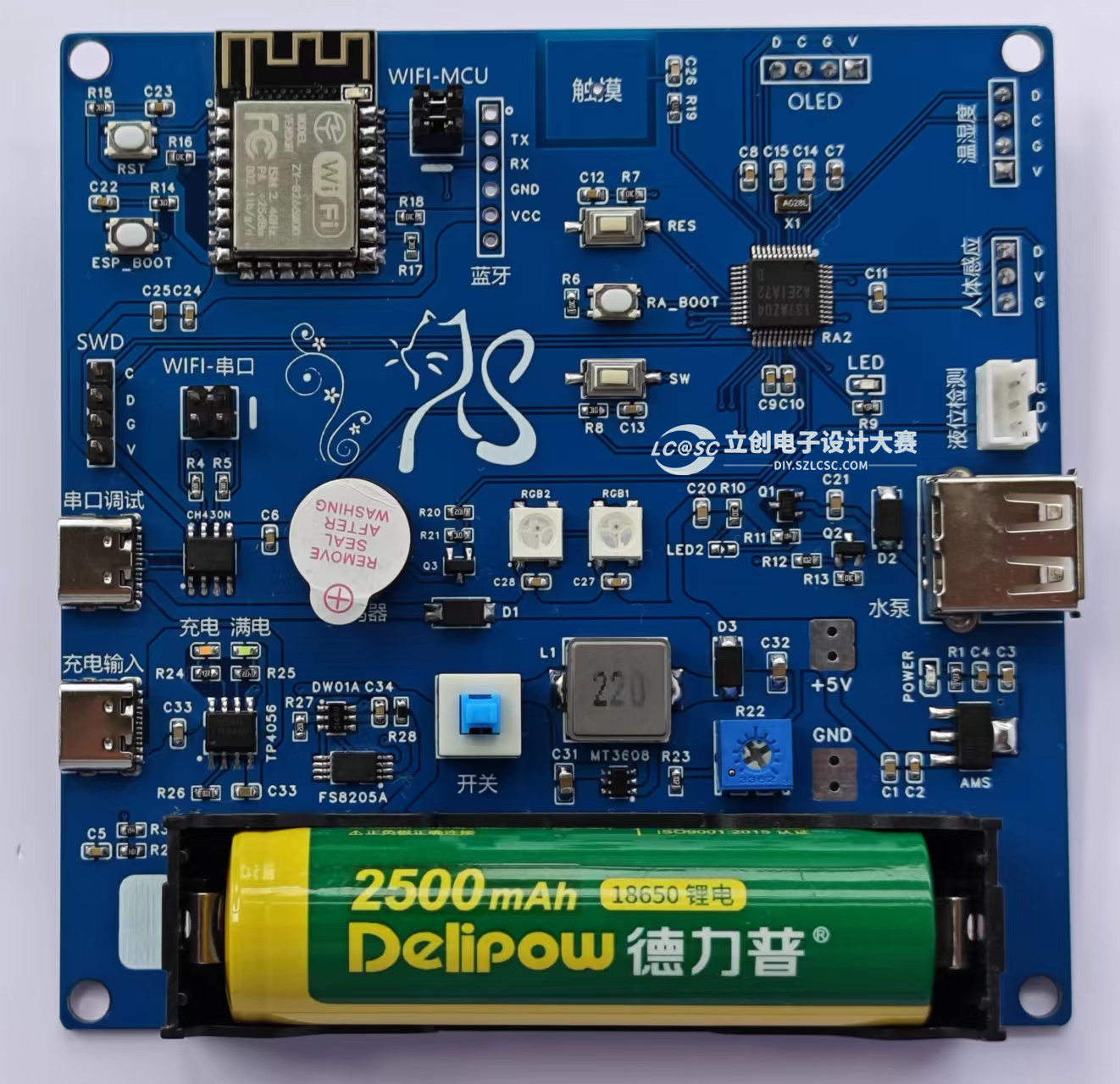
Physical drawing of the circuit board

Temperature and humidity, human body sensing, OLED module

The front of the smart water dispenser

Side of smart water dispenser (charging port)
Hardware circuits
1. MCU core circuit


R7FA2E1A72DFL chip features:
- 48MHz Arm® Cortex®-M23
- 64kB of flash memory and 16kB of SRAM
- 4kB data flash memory for EEPROM-like data storage
- Wide operating voltage range of 1.6V - 5.5V
- Enhanced Capacitive Touch Sensing Unit (CTSU)
- 12-bit ADC, LPACMP, temperature sensor
- 32-bit general-purpose PWM timer, 16-bit general-purpose PWM timer, low-power asynchronous general-purpose timer
- Real-time clock
- SCI (UART, Simple SPI, SimpleI2C)
- Separate SPI interface/I2Cmulti-master interface
- Security features
- Encryption
2.WIFI circuit (can be replaced with bluetooth)

ESP8266 it's best to buy one with AT firmware when you buy it, and if you don't have it, you need to download it yourself.

3. Liquid level detection sensor, human body sensing sensor, temperature and humidity sensor, OLED module.

Liquid level sensors

Body sensing sensor

Fast response, low static power consumption, high sensitivity, small size and simple installation, the lens has been installed and the pin header has been welded, and the power supply is matched, no need to debug
Feature Description:
1. The output high level time of this product is adjustable, from 2.5 seconds to 1 hour, and the output time set at the factory is 2.5 seconds
2. Blocking time, 2 seconds, non-adjustable
3. The factory definition is repeatable triggering and cannot be changed
4. The power supply voltage of this module is 3.3V to 15V, and the limit voltage is 2.8V to 18V5. If the delay time is changed, the time of the module powering on the output high level will increase accordingly, which can be understood as the start-up time to enter the normal working state after power-on will increase6, after installing the photosensitive original price, it does not work during the day, works at night, does not install the photosensitive element, and works all day (the default is that there is no photosensitive element installed) 7, this module is very sensitive, pay attention to the installation position, and try to avoid the heat source radiation source (air outlet/yang)
5. The sensitivity of this module is adjustable, and a chip resistor needs to be changed
Temperature and humidity sensor (note the pin order)

1. Humidity measurement range: 0~100%RH
2. Humidity measurement accuracy: ±3%RH
3. Temperature measurement range: -40~125°C
4. Temperature measurement accuracy: ±0.3°C
5. Working voltage: 2.4~5.5VDC (wide voltage)
6. I2C interface output
0.96 inch OLED module (note pin order)

1. High resolution: 128*64.
2. Ultra-wide viewing angle: greater than 160°.
3. Ultra-low power consumption: 0.06W during normal display.
4. Wide power supply range: DC 3.3V-5V.
5. Industrial grade: working temperature range -30C~70C.
6. Small size: 27mm*27mm*2mm.
7. Communication mode: IIC.
8. Brightness and contrast can be controlled by program instructions.
9. The service life is not less than 16,000 hours.
10. OLED screen internal driver chip: SSD1306.
4. Water pump circuit


When the output of P111 is high, the water pump is turned on (LED2 is on):
R_IOPORT_PinWrite(&g_ioport_ctrl, WaterPump, BSP_IO_LEVEL_HIGH);//Turn on the water pump
R_IOPORT_PinWrite(&g_ioport_ctrl, WaterPump, BSP_IO_LEVEL_LOW);//Turn off the water pump
5. Buzzer, RBG circuit


When the P104 outputs high, the buzzer sounds:
R_IOPORT_PinWrite(&g_ioport_ctrl, Buzzer, BSP_IO_LEVEL_HIGH);//Turn on the buzzer
R_IOPORT_PinWrite(&g_ioport_ctrl, Buzzer, BSP_IO_LEVEL_LOW);//Turn off the buzzer
WS2812b Core Display Code:
setPixelColor(i, green, red, blue);//The number of WS2812B color values (transmitted via SPI).


6. Serial port debugging circuit


By default, it is directly connected to the RA MCU, and the jumper can be used for programming and debugging ESP8266.
 Type-C access can be used to print debugging information, as shown in the date shown in the figure above.
7. Battery level detection

The upper and lower voltages of 18650 lithium batteries are 4.2V and 2.75V, respectively.
The nominal voltage of a single cell of 18650 lithium battery is generally: 3.6V or 3.7V.
The minimum discharge termination voltage of 18650 lithium battery is generally: 2.75V, below which it is easy to cause serious decline in battery capacity and even scrap. Most lithium battery discharges cannot put the no-load voltage below 3.2V, otherwise excessive discharge will damage the battery.
In the program, we set the battery voltage to be less than 3.6V to sound an alarm and turn off the water pump and RGB.
8. Power supply circuit (lithium battery charge and discharge protection, boost, LDO)


(It is best to solder the power module first, debug the 5V output, and then solder other modules)
Maximum charging current: 1000mA
Charging cut-off voltage: 4.2V
Battery over-discharge protection voltage: 2.4V
Maximum Output Current: 2A (within 1A recommended)
Output voltage: 4~12V
Type-C power input, red light is always on, indicating charging. The blue light lights up when fully charged. When there is a power supply at the input end, the current is obtained from the power input terminal, and if it is not connected to the power supply, the current is obtained from the battery, and the output is automatically turned off when the battery voltage is lower than 2.4V. When the battery is connected for the first time, there may be no voltage output, and the protection circuit needs to be activated by powering on the power input. When using a mobile phone charger for power supply, it must be able to output more than 1A, otherwise it may not be able to charge normally.


Software code
Pay attention to changing the WiFi account and password for the copy project.
Please refer to the attachment for details of the code project.

ESP8266 initialization and related code at:
ESP8266.c and ESP8266.h
OLED initialization and related code at:
oled.c、oled.h、oledfont.h
SHT30 initialization and related code are available at:
sht3x.c and sht3x.h
WS2812B initialization and related code are available at:
WS2812B.C and WS2812B.H
The main program is written in hal_entry.c
Designed by yt17 (from OSHWHub)
Design Drawing
 The preview image was not generated, please save it again in the editor.
 Empty
Empty


Comment