

 Completed
# 8th LC Electric Race # Desktop clock/desktop energy storage station/snow light base
PRO # 8th LC Electric Race # Desktop clock/desktop energy storage station/snow light base
License
:GPL 3.0
Description
*-1. Update records
2023/07/30 Please do not break the board, there is a problem with the current version.
2023/08/01 It can be fought, but there are expedients.
*0. BUG record
0. Major BUG, unknown solution
Scenario recurrence: All installations are completed. When the clock board is not connected to the external power supply, the battery board should be powered externally at this time, but the power supply fails;
Disconnect the clock board and battery board, and the functions will be normal;
(Due to design issues, the VCC network of the clock board does not directly supply power to the chip, but is connected to the 5V network through 1N5819. After connecting VCC and the 5V pad with flying wires, power is supplied from TypeC, and the clock board functions normally;)
It is speculated that due to the unknown connection between VCC and 5V, we tried to connect only the 5V and GND copper posts of the clock board and the battery board, but the measured power supply failed; (and the battery board cannot supply power to the outside at this time)
1. Do not weld AO3401A, the pmos tube will cause abnormal function!
2. When connected to the power supply, the two green lights on the front are too bright;
3. I forgot to drill holes in the middle GND pad of ip5306 for heat dissipation.
4. The inductor occasionally whistles, please consider replacing the inductor.
*1. Introduction to Project Functions
This project is based on the LC Electronics Competition in July 2023: "Desktop Electronic Clock Design Based on Renesas". A battery module, that is, a desktop energy storage design, is added to the original desktop clock design.
Note: The design of this project is based on my existing components, and some of the designs are a bit cumbersome. If you need to reproduce, please update the normal version in the comment area.
Note: There is no limit to the theme. It can be a solution to a certain problem in life/work, a plan designed for a certain group of people/scenarios, graduation project/course design/DIY project/purely cool project, etc. Mainly talk about what problems you solved by what means.
*2. Project Attributes
This project was made public for the first time. I drew the schematic diagram and PCB by myself with reference to the original design of the LC Electronic Competition. I have not participated in other competitions and have not participated in the defense.
Note: Please indicate whether the project has been made public for the first time; whether the project is original; whether the project has won awards in other competitions; if so, describe the details of the award; whether the project has participated in a defense in school.
*3. Open Source Agreement
GPL(GNU General Public License):GNU General Public License.
Note: Altruism means self-interest, please read the following content carefully.
1.Embrace open source and give projects unlimited value. It is recommended that more than 80% of the core functions of the project be open source;
2.If a certain part of the function is irreplaceable and the project cannot solve the corresponding problem after deletion, then the function implemented by this part is the core function of the project; for example, if an electronic load is designed and a host computer software is designed to monitor power changes, the electronic The load is the core function, and the host computer software is the auxiliary function; for example, an isolated 485 module is used in the electronic load to communicate with the host computer, then the communication function implemented by this 485 module is an auxiliary function;
3.Projects should choose an open source license that suits them. If the project references other open source projects, the source should be indicated and follow the original author's open source license regulations. It is recommended that original projects use the GPL3.0 open source license;
4.Functions implemented by directly quoting the original circuits or original codes of open source projects cannot be used as the core functions of one's own projects, and functions directly implemented using common modules on the market cannot be used as core functions of one's own projects.
*4. Hardware Part
The project consists of two PCBs: clock board and battery board.
Note: PCB size is 100*61.8mm.
Clock Board
The schematic diagram basically refers to the official design ideas, only some components are replaced (such as the micro switch is replaced with a vertical switch, the RST and BOOT switches are replaced), the layout is adjusted, and silk screen is added;
Battery Panel
The battery management chip was replaced from the original design TP4056 to IP5306;
IP5306 schematic design reference data manual and the design of IP5306 dual USB power bank by a master who accidentally entered the strange picture - JLC EDA open source hardware platform (oshwhub.com)
 Figure 1 IP5306 schematic design
Note 1: The button control of pin 5 is not added. The actual test found that there is no need to use IP5306_CK. IP5306 can automatically detect load access and automatically boost the voltage;
Note 2: The output voltage of IP5306 after automatic sleep is about 2.3V (battery voltage 3.9V);
Note 3: IP5306_CK is a 5V normally open version.
The battery module is changed from the original design soft pack battery to Sanbin SMD 18650 battery;
Because I don’t like flying cable connections, I think this is more elegant.
The output terminal is 1*Type_A female connector (4pin SMD version) + 2*Type_C male connector (9pin sinker SMD version);
Note: The Type_C male connector is designed to only supply power to the outside (if it is used as a snowflake lamp base), please do not supply power to it (you must be a novice if you can charge it from here, right awa)
For the right Type_C male connector, a voltage dividing resistor was added according to the design manual. The effect is unknown due to insufficient equipment...
Note: The resistors used are all existing resistors connected in series. You can use a resistor to replace it by yourself/replacement.
Note: It is recommended to use JLC EDA . If you choose other EDA tools, please upload schematics in PDF format, PCB drawings in PDF format, and PCB files in Gerber format in the attachments. Here you can explain in detail your project implementation principles and mechanisms, precautions, debugging methods, testing methods, etc. It is recommended to introduce your ideas to others in the form of pictures and texts.
*5. Software Part
From training camp, unmodified.
Note: If your project involves software development, please upload the corresponding project source code in the attachment. Here you can describe in detail your software flow chart, functional module block diagram, explanation or popular science of related algorithms, source code structure, construction and configuration of compilation environment, source code compilation method, program burning method, etc. It is recommended to introduce your ideas to others in the form of pictures and texts.
*6. BOM List
Please refer to the automatically generated list, and the resistance, capacitance, and chip silk screen have been marked on the PCB.
Note: BOM list involved in the project. Please upload a screenshot of the BOM at this location. Please upload the list details in PDF format to the attachment. Suggestions include model, brand, name, packaging, procurement channels, usage, etc. The specific content and form should be based on clearly expressing the project composition.
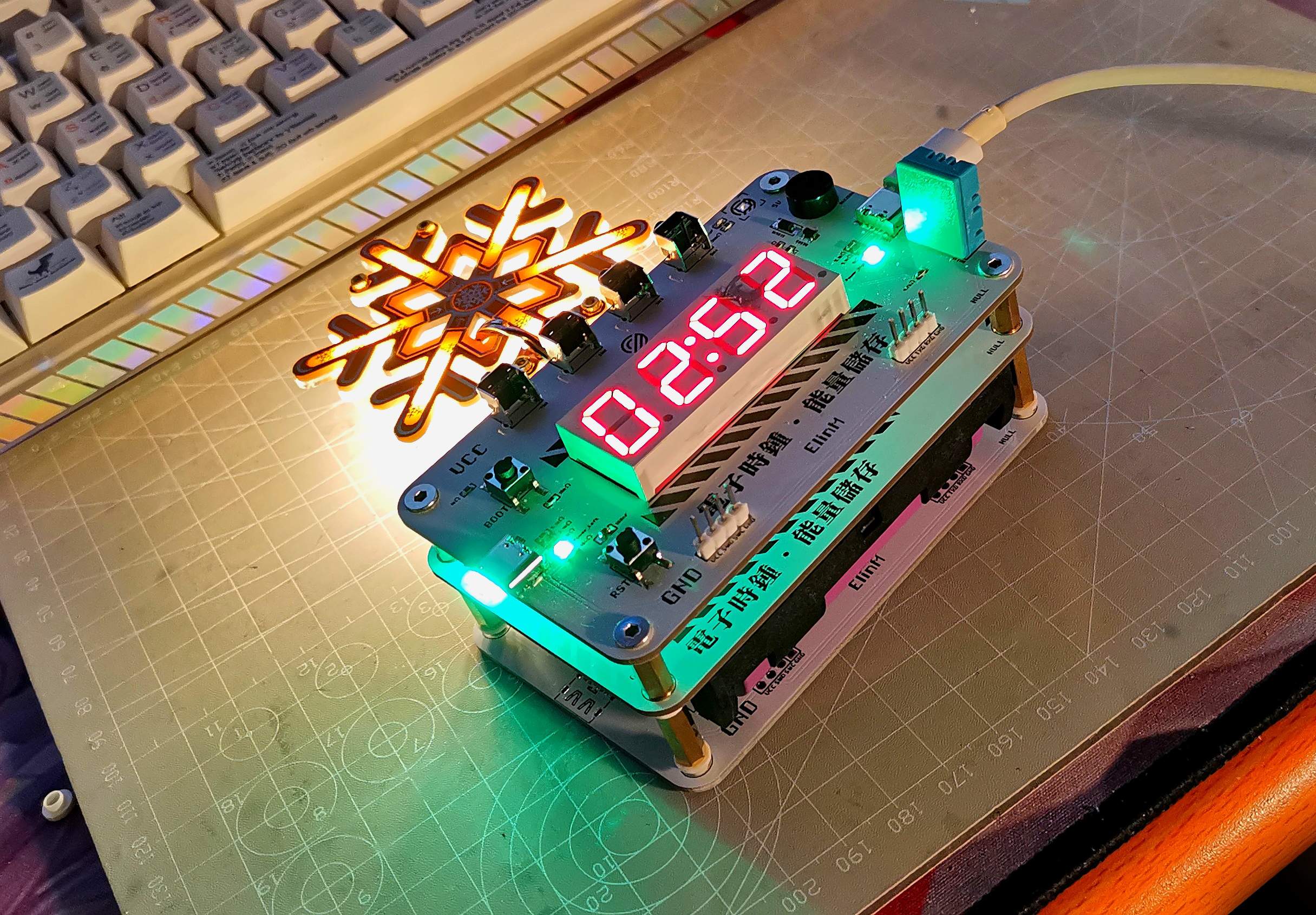
*7. Contest LOGO verification

Figure 2 Actual picture
Please upload a project picture containing the competition logo. The logo will be printed on the PCB in the form of silk screen printing.
Click the zip to download the competition logo! (Contest logo).zip
*8. Demonstrate your project and record it as a video for uploading
https://www.bilibili.com/video/BV1iu4y127yq/
Video requirements: Please shoot horizontally, with a resolution of no less than 1280×720, in Mp4/Mov format, and the size of a single video is limited to 100M;
Video title: Lichuang Electric Competition: {Project Name}-{Video Module Name}; such as Lichuang Electric Competition: "Autonomous Driving" - Team Introduction.
More details: https://diy.szlcsc.com/posts/15a52db9fd7d40c492eb505280278e45
*9. More Pictures


*10. Expedient measures

Expedient measures when BUG0 is not yet resolved:
1. Use two sets of boards to cooperate;
2. For the first set of boards, please solder all the components of the clock board + the 1N5819 diode of the battery board;
3. For the second set of boards, please solder Type_C of the clock board and four 5.1k resistors + all components of the battery board;
4. For one group of boards, please use copper pillars to connect the boards. For two groups of boards, please use plastic pillars to connect them.
5. You're done. At this time, the functions of the two groups are independent of each other, and the battery board can supply power to the clock board through the data line!
Designed by elinm (from OSHWHub)
Design Drawing
 Empty
Empty
Comment