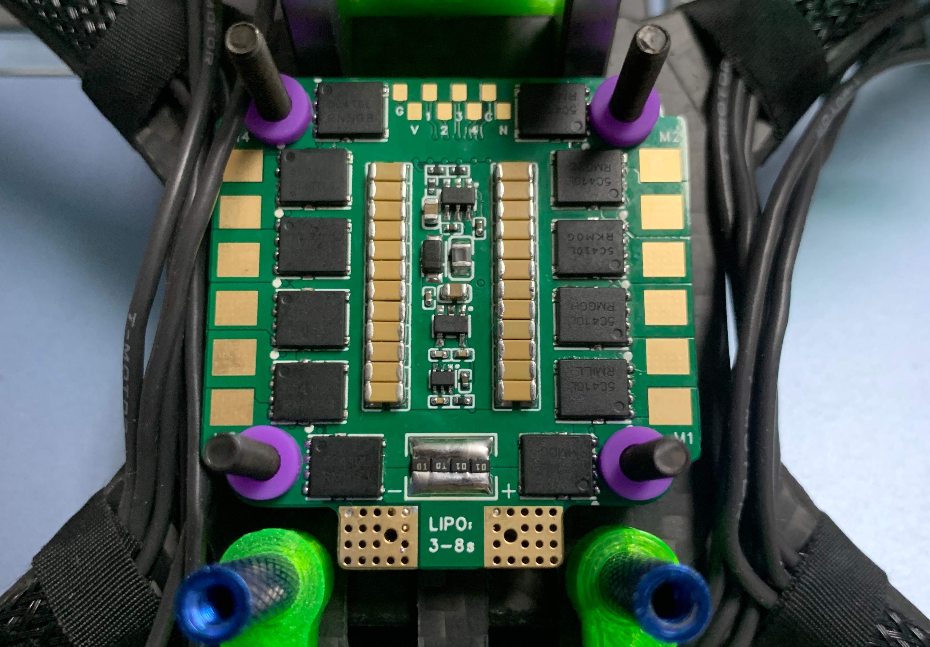
 Completed
4-in-1 ESC version 30.5mm based on BLHeli_S firmware
PRO 4-in-1 ESC version 30.5mm based on BLHeli_S firmware
License
:CC BY-NC-SA 4.0
Description
The ESC uses an open-source firmware BLHeli_S with a firmware type of J-H-30 and is compatible with Bluejay firmware.
BLHeli_S firmware address:GitHub - bitdump/BLHeli: BLHeli for brushless ESC firmware
Bluejay firmware address:GitHub - mathiasvr/bluejay: Digital ESC firmware for controlling brushless motors in multirotors
The flashing tutorial and firmware are in the attachment, please pick it up.
This ESC adopts 4+6 layer board design in hardware design.
Among them, the 4-layer board is the half-hole core board of the control part, and the recommended plate thickness is 1mm. At the same time, due to the free PCB process, there may be some cases where the half hole of the board is not firm, please check whether the half hole is connected normally after receiving the board.
The 6-layer board is the MOS tube high-current part, the DC-DC power supply part and the current detection part, due to the change of JLC proofing rules, it cannot pass the review after playing the board according to the rules, that is to say, an account can only play the 6-layer board once.


As for the question "how many A is this ESC", since the ESC test environment requires at least 1,000W of power supply and electronic load, if you want to know the overcurrent capability, I suggest you sponsor me with a strong enough power supply and load. I have carried out the actual flight test under the voltage condition of 6S, the motor is four Chengfeng 2207 1950KV version, and the propeller is 51466 propeller.
There are a few things to keep in mind when making it:
1. The main thing to pay attention to is the selection of high-voltage devices, the maximum withstand voltage of the ESC is 40V input, for the reserved margin, it is recommended to be 3~8S, and the TVS needs to be selected according to the input voltage to avoid the damage to the circuit caused by the back electromotive force caused by the motor deceleration, followed by the input filter capacitor needs to consider the withstand voltage capacity (including the input capacitance of DCDC), I choose the 50V MLCC capacitor.
2. Due to the limitation of 30.5mm positioning holes, the metallization part of the four positioning holes is one of the four ESCs, and it is necessary to pay attention to the isolation treatment of rubber shock-absorbing pads when using.
3. The filter capacitor part is 1206 47uf 50V MLCC capacitor*24 (yes, although I drew the 0805 package, I recommend that you solder 1206.) The total theoretical capacitance has exceeded 1mf, and I did not choose to add a large capacitor electrolytic capacitor externally, because the excessive capacitance will lead to a more serious "ignition" situation at the moment of power-on, and I do not agree with some people's "superstitious" statement about capacitance and image transmission definition, and it is TVS rather than capacitor that plays a greater role in suppressing motor back EMF.
4. The current sampling resistance part is drawn as a reverse polarity resistance of 1225, but due to price reasons and overcurrent capacity, the personal use is 1206 1mΩ 1W*4 for parallel processing, the equivalent is 0.25mΩ, and the power dissipation under the current that can theoretically carry a larger current than the 1225 resistor, according to this situation, the BF galvanometer part is set to 125.
5. Regarding the selection of MOS tubes, if you ask me, I will only recommend you 5c410, a treasure can search for 5c410 MOS, the disassembly piece is about one yuan, and the estimated production cost is less than 100.
6. The control part is completed by SJJ, due to the engineering version, the schematic diagram cannot be provided, if necessary, you can wait for him to open source after viewing or go to my open source single electrical survey to see.
7. Part of the attachment is the tutorial of burning, and the other part is the PCB Gerber modified according to the 2Oz copper thickness rule of JLC, which can also be used to play 1Oz boards, you are happy.
If you have any other production questions, please join the penguin flock 479926321 and ask your questions in the group or contact the group owner directly.
Note: There is no reminder means for private messages on open source platforms, so it is easy to ignore private messages!
Designed by mtbsk8 (from OSHWHub)
Design Drawing
 The preview image was not generated, please save it again in the editor.
 Empty
Empty


Comment