

 Completed
32-bit 4-1 MK 1.1
PRO 32-bit 4-1 MK 1.1
License
:CC BY-NC-SA 4.0
Description
Project Description
A 32-bit brushless 4-in-1 ESC based on AM32/HF32 firmware, suitable for multicopters, climbing vehicles, boats and other fields.
Open-source Protocol
This hardware is designed to be released under the CC-BY-NC-SA 4.0 license, which is only for hobbyists to use for DIY learning and communication, and any form of commercial use is strictly prohibited. This design is provided as is, without any form of work guarantee/after-sales warranty, and is not responsible for the consequences and joint liability for any damage/damage to the personal and property resources of the producer and third party caused by improper product design and operation and violation of local laws and regulations.
CC-BY-NC-SA 4.0, Creative Commons License - Attribution - Noncommercial Use - ShareAlike.
CC: Abbreviation for Creative Commons license.
BY: Attribution, you must give appropriate attribution, provide a link to this License, and indicate whether or not changes have been made (to the original work).
SA: Share Alike, if you mix, transform, or create based on the work, you must share and distribute your contribution under the same license agreement as the original license.
NC: Non-commercial use, you may not use this work for commercial purposes without permission.
Project-related Features
Product Overview
-
-
- 32-bit processor: Based on a 32-bit processor, it provides higher processing performance and accuracy for higher levels of flight control.
- 4-in-1 design: Four independent ESCs are integrated, which is convenient for users to install and debug in small multicopters. Reduced wire connections and onboard space.
- Support a variety of motor protocols: servo PWM, Dshot300, Dshot600.
- On-board galvanometer design: The real-time current can be viewed through the flight control ground station. (Power baseplate on-board)
- Wide range of speed regulation: It has a wide range of speed regulation, allowing users to adjust according to different application needs.
- Configuration Tool: A visual configuration tool Esc_Config_Tool is provided, allowing users to easily adjust parameters and configure the ESC to suit different flight needs.
- Firmware upgrades: Firmware upgrades are made through Esc_Config_Tool so that users can enjoy new features and performance improvements over time.
- Lightweight design: The compact design is adopted to reduce the volume of the PCB as much as possible while maintaining the same performance, so as to meet the weight and space requirements of the aircraft.
- Open Source Firmware:The AM32 firmware is open-source, and users can modify and customize it themselves according to their needs.
- Wide range of application: suitable for multicopters, climbing vehicles, boats, etc.
-
Product Parameters
-
-
- Size: 29.6mm*22.6mm*4mm (control part half-hole core plate) 40.559mm*47.201mm*5mm (MOS tube high power part bottom plate) 40.559mm*47.201mm*7mm(ESC)
- Working voltage range: 10~40V, it is recommended to use 3~6s model aircraft battery power supply, the limit is 8s.
- Master Control:AT32F421K8U7: Artery Technology ARM® Cortex-M4® microcontroller, up to 120MHz CPU computing speed and built-in digital signal processor (DSP), supporting up to 64KB Flash memory (Flash) and 16KB random access memory (SRAM).
- Gate Driver: FD6288Q: Integrates three independent half-bridge gate driver IC chips, designed for high-voltage, high-speed drive MOSFETs and IGBTs, and can operate up to +250V.
- Galvanometer:INA199: Bidirectional, Zero Drift, Low-Side or High-Side, Voltage Output, Current Shunt Monitor.
- Buck: A step-down DC-DC converter capable of delivering 3A using SY8303 high-efficiency synchronous rectification to power the gate driver with a supply voltage down to 8V.
- LDO: CJA1117B-3.3 low-dropout linear regulator is used to supply power to the 32-bit main control.
- PCB design: The design of the control part of the half-hole core board and the MOS tube high-power part of the bottom plate is separated, in which the core board is designed with 4 layers of boards and the bottom board is designed with 6 layers of boards.
- Firmware:AM32/HF32
-

Project Properties
This project is the first public and is my original project. The project has not won an award in another competition.
Project Progress
2024/01/01 -- 2024/02/16 The hardware part of this ESC was designed with JLC Professional Edition.
2024/02/17 -- 2024/03/25 Wait for proofing and learn the open source firmware AM32/HF32.
2024/03/26 -- 2024/03/27 Soldering circuit.
2024/03/28 -- 2024/04/01 Test the relevant functions of the ESC and test the flight on the plane.
Design Principles
Hardware Block Diagram
Four-in-One Electronic Speed Controller (4-IN-1 ESC). The hardware part is mainly composed of a core processing unit, a power management unit, a back electromotive force detection circuit, a gate drive circuit, a three-phase inverter bridge circuit, a current detection circuit, etc.

Power Management Unit

Low-dropout linear regulators are partially selectedThe CJA1117B-3.3 has a fixed output voltage of 3.3V, a current output capability of 1A and extremely low noise characteristics, which is suitable for power supply for the four masters of the ESC.

Among them, R1 is the upper voltage divider resistor, and R2 is the lower voltage divider resistor. According to the above formula, when the output voltage of the BUCK circuit is required to be 8V, R1 chooses 110KΩ, R2 uses 9.1KΩ. Schematic diagram of the BUCK circuit, as shown in the figure.

Back EMF Detection Circuit
The back EMF detection circuit of the electronic governor is mainly composed of a voltage divider circuit and a zero-crossing comparison circuit.
The brushless DC motor uses an electronic controller to sequentially excite the windings on the stator to generate a rotating magnetic field. After that, the resulting rotating magnetic field interacts with the permanent magnets on the rotor, resulting in an electromagnetic torque that drives the rotor to rotate. The electronic controller must know exactly the real-time position of the rotor, because we can only commutate the rotor after it has reached the predetermined position, so that the motor can run smoothly. There are three commonly used methods for rotor position detection:
(1) Based on the voltage-crossing comparison, the rotor position is detected by comparing the three-phase voltage with the neutral point voltage of the motor. The advantage is that there are fewer connecting wires and the hardware circuit is simplified. The disadvantage is that open-loop control is required at start-up, which can lead to poor control performance at low speeds and complex hardware circuitry.
(2) The position of the rotor is detected by installing Hall and three Hall sensors spaced 120 degrees apart on the motor, and the position of the rotor is detected by the change of the magnetic field. Hall sensors provide precise information about the position of the rotor's magnetic poles, enabling accurate commutation control. The advantage of this method is that the circuit structure is simple, but it will increase the cost of the motor.
(3) Magnetic encoder is installed to directly detect the exact position information of the rotor. This method is costly and is often used where high-precision position feedback is required.
After a detailed comparative analysis, it was decided to use a voltage-based zero-crossing comparison to detect the rotor position, as drones usually do not need to operate at low speeds, thus avoiding the problem that zero-crossing comparisons are poorly controlled at low speeds. In addition, the brushless motor drive system with sensorless control strategy simplifies the hardware architecture of the system and reduces the number of connections between the motor and the driver, thereby reducing the overall system complexity. In addition, the cost and stability of the system are effectively controlled due to the reduced use of external components. The purpose of the voltage divider circuit is to reduce the back EMF generated by the motor windings to the voltage range that the microcontroller can handleIt provides the necessary voltage reference for the control of brushless motors. The purpose of the zero-crossing comparison circuit is to capture a zero-crossing signal by capturing a zero-crossing signal when the back EMF gradually rises from negative to exceed the neutral voltage of the motor during operation, or when the back EMF gradually decreases from positive to below the neutral voltage of the motor. This serves as feedback on the rotor position. This feedback enables the electronic control unit of the motor to accurately identify the optimal timing of current commutation, resulting in smooth operation and efficient conversion of the motor, ensuring the continuity and stability of the power output. Schematic diagram of the back EMF detection circuit, as shown in the figure.

Gate Drive Circuitry
Gate driver chip selectionFD6288Q, the main reason is that the chip integrates three independent half-bridge gate drivers, which reduces the number of external components and thus the risk of failure. In addition, the FD6288Q supports high-voltage operation, has high-speed switching characteristics, and has built-in protection mechanisms such as over-current protection and under-voltage lockout, which enhances the overall stability of the system. Bootstrap diodes and bootstrap capacitors are key components of gate drive circuits, and the functions of both components are explained below and the key points to be aware of when selecting them.
The role of the bootstrap diode is primarily to provide a charging path in the gate drive circuit so that the bootstrap capacitor can be charged and maintained at the desired voltage level during each switching cycle. When the low-side switch is turned on, the bootstrap diode will allow current to flow through to charge the bootstrap capacitor, while the bootstrap diode also helps protect the stability of the gate drive circuit by helping to prevent voltage overshoot and noise in the gate drive circuit. When choosing a bootstrap diode, you need to choose a diode with a high reverse breakdown voltage and a short reverse recovery time. This is because the high reverse breakdown voltage ensures that the bootstrap diode can withstand high voltage impulses when switching on the high side. The short reverse recovery time means that the bootstrap diode can quickly switch from the forward conduction state to the reverse cut-off state. In brushless motor drive applications, the short recovery time results in higher switching frequencies and reduces energy losses during switching conversions, thus improving the control accuracy and responsiveness of the motor. Based on the above two characteristics, the 1N4148WTQ-7 switching diode is selected as the bootstrap diode in this design. Its reverse breakdown voltage of 80V and reverse recovery time of 4.0 ns ensure high reliability and stability in high-frequency switching operation.
The role of a bootstrap capacitor is to store energy to supply voltage to the gate drive circuit when needed. In a half-bridge drive circuit, the bootstrap capacitor is charged through the bootstrap diode when the low-side switch is turned on, and when the high-side switch is turned on, the bootstrap capacitor is discharged through the output of the gate driver to provide voltage to the gate of the high-side MOSFET.

Where Cbs is the capacitance of the bootstrap capacitor, Qg is the gate charge of the MOSFET, Vcc is the supply voltage of the FD6288Q, and Vf is the forward voltage drop value of the bootstrap diode.
From the design of the ESC's power management unit, the Vcc is 8V, and the Qg is 143nC and the Vf is 1V according to the data sheets of the MOSFET and diode. Substituting the values of the above three variables into the above formula yields the capacitance of the bootstrap capacitance, with a minimum value of 204.29nF. According to the calculation results, considering that if the bootstrap capacitor is much larger than the calculated 204.29nF, it will increase the charging and discharging time of the circuit, and affect the response speed and dynamic performance of the system. If a capacitance value of less than 204.29nF is chosen, there is no capacity to store enough charge to provide sufficient transient response, resulting in insufficient gate drive voltage. Finally, a ceramic capacitor with a capacitance of 1μF, a withstand voltage of 50V, and a package of 0402 was selected to ensure high reliability and stability in high-frequency switching operation. Schematic diagram of the gate drive circuit, as shown in the figure.

Three-phase Inverter Bridge Circuit
The three-phase inverter bridge circuit consists of sixThe MOSFET is composed of an upper and lower side arm, and each arm has three switching devices to control the on/off of the three-phase current. The gate pull-down resistor of the MOSFET plays a crucial role. When the MOSFET's drive signal is revoked, the pull-down resistor provides a discharge path that allows the gate capacitor to discharge quickly. This process ensures that the MOSFET can be switched off quickly and accurately, avoiding wasted energy and potential thermal damage due to untimely withdrawal of the drive signal. At the same time, the presence of a pull-down resistor ensures that the MOSFET remains in a stable shutdown state with a low potential in the absence of a driving signal, effectively preventing malfunction due to external interference or internal noise. When selecting a MOSFET, consider that the drain-to-source voltage of the MOSFET must be higher than the input voltage of the ESC and the voltage spike generated by the back EMF of the motorThe continuous drain current should be able to withstand the maximum current in the circuit. In addition, it is also necessary to consider the on-resistance of the MOSFET, which is the equivalent resistance of the MOSFET when it is turned on, which generates heat when current passes through it, and choosing a MOSFET with low on-resistance can help reduce power loss and improve efficiency. Considering the above three points, the design chooses NTMFS5C410NL, and the relevant parameters of the MOSFET are as follows: Vds is 40V. At 100°C ambient temperature, the maximum continuous drain current is 230A. At a gate-to-source voltage of 10 V, the minimum and typical on-resistance values are 0.65 mΩ and 0.82 mΩ, respectively. Schematic diagram of the three-phase inverter bridge circuit, as shown in the figure.

Current Detection Circuits
The purpose of the current detection circuit is to accurately measure the total current flowing through the phase line of the motor in an electronic governor. Divide the battery capacity by this current, and the result is how long the battery can be used. Through the above calculations, it is possible to determine the remaining usage time of the drone. The galvanometer is a bidirectional, low-side, zero-drift, voltage-output current sense amplifier with a INA199A, and the circuit schematic diagram is shown in the figure.

Software Description
- Firmware description: (currently using version 1.99 AM32 firmware) The firmware of the product uses the AM32-MultiRotor-ESC-firmware open source on github.
- AM32 firmware address: GitHub - AlkaMotors/AM32-MultiRotor-ESC-firmware: Firmware for stm32f051 based speed controllers for use with mutirotors
- The AM32 has the following features:
- Firmware upgrade via BetaFlight pass-through, single-wire serial, or Arduino, (Powerwriter recommended)
- Servo PWM, Dshot (300, 600) motor protocol support
- Servo PWM, Dshot (300, 600) motor protocol support
- KISS standard ESC telemetry
- Variable PWM frequency
- Sinusoidal start mode designed to accelerate larger motors
Firmware Flashing Procedure
(1) Solder the half-hole core board of the control part of the ESC for the first time, and then you need to burn the bootloader (this burning step needs to be performed 4 times), the burning tool and the burning file will be put into the attachment, and you need to prepare the Powerwriter burner (as shown in the figure below).

(2) Take out the powerwriter programmer and connect it to the programming point of the half-hole core board of the ESC control part, the programmer VREF (3.3v) is connected to V, gnd is connected to G, swclk is connected to C, and swdio is connected to D.
(3) Open Power Writer to connect to the target chip

(4) Connect the target chip AT32F421x8 and click "Program Memory"

(5) Load the bootloader.hex file (AM32_F421_PB4_BOOTLOADER_V4.hex) and click "Write". (For details of the hex file, please refer to the attached "AM32 Firmware Information").

Repeat the above steps 4 times to flash the bootloader to all four AT32 masters
(6) Connect the S1, S2, S3 and S4 ports of the half-hole core board of the control part with the motor interface of the flight controller respectively, and remember to pay attention to the order, that is, S1~S4 are connected to the motor 1~4 of the flight controller in turn. And change the ESC protocol of the flight controller to DSHOT600.
(7) Open Esc_Config_Tool to burn the AM32 firmware, note that you need to select M1 M2 M3 M4 by yourself, and you also need to repeat the AM32 firmware 4 times.
(For details of the firmware, please refer to the attachment "AM32 Firmware Information")

(8) So far, the AM32 firmware has been programmed for the ESC. Subsequent firmware updates only need to be repeated in steps (6) and (7).
PS: HF32 firmware can also be flashed. The burning steps are shown in the video.
Physical Display
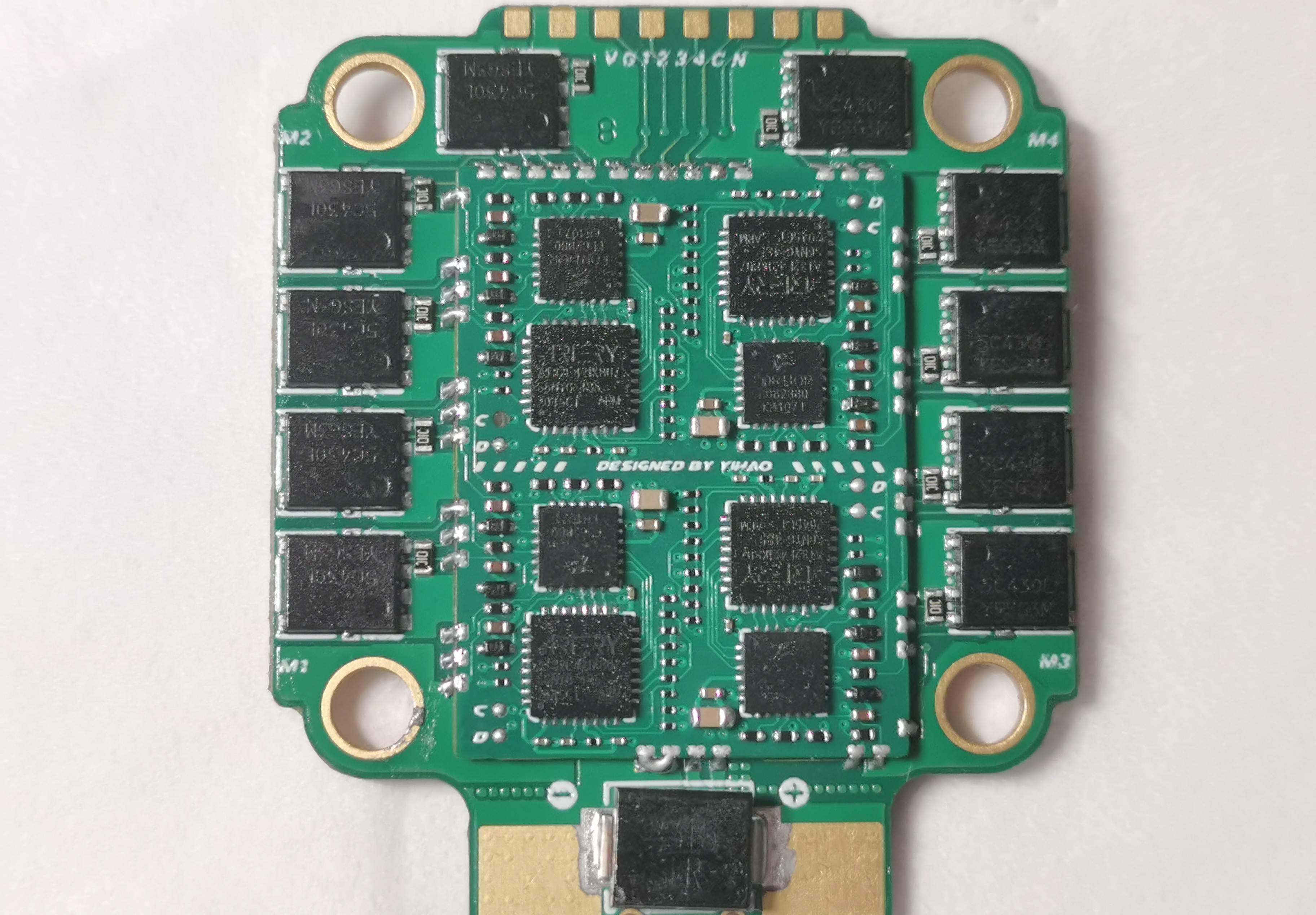
The PCB of the 4-in-1 ESC is designed as a stacked board, because the current flowing between the drain and source of the MOSFET is very large, and by soldering the half-orifice plate of the control section to the base plate of the power section, a shorter path can be created for the high-current traces, thereby increasing the overcurrent capability of the ESC.
The control half-orifice plate is designed with four layers of plates, and the stacking relationship is signal (top layer) - reference ground (inner layer 1) - power supply (inner layer2)- Signal (bottom layer).
The power base plate is designed with six layers, three of the six layers are the power supply layer and the third layer is the ground layer. In addition, the high-current trace part adopts the windowed tin stacking technology, which can achieve wider traces in the high-current area, so as to further improve the overcurrent ability of the ESC. MLCC) is used to filter the power supply and absorb voltage spikes generated by the back EMF of the motor. MOSFETs are laid out close to the connected motor phase wires to shorten trace lengths, reduce resistance, and optimize overall performance. The actual circuit board of the 4-in-1 ESC is shown in the figure below.

Fig. (1) The front of the 4-IN-1 ESC and (2) The back of the 4-IN-1 ESC
Demo Video
Design Considerations
This design is provided as is, without any form of job security/after-sales warranty, and shall not be liable for any consequences and joint and several liabilities of damage/damage to the personal property resources of producers and third parties caused by product design, improper operation and violation of local laws and regulations.
- The control board and the power board are connected by the stamp holes around it, and pay attention to the direction of placement.
- It is difficult to reproduce this project, the minimum part is 0201 package, there is a certain degree of difficulty in welding, it requires very good patience (it may take multiple debugging, or even blowing up the machine), as well as good learning ability, and can solve the difficulties encountered in different ways, including but not limited to welding, flashing firmware, and reasonable use of firmware. Therefore, it is only recommended that those who have played with drones and are proficient in soldering SMD components and have a certain understanding of PCBs and components can reproduce them.
- Selection of power supply voltage: The ESC theoretically has a maximum of 40V input, which is reserved for margin, and it is recommended to use 3~6s model aircraft battery for power supply, with a limit of 8s (not recommended).
- Selection of components: It is necessary to select the filter capacitor according to the input voltage (it is recommended that the capacitor be purchased in the JLC Mall, and the phenomenon of TB false standard is rampant).
- When soldering, please use a silicone wire (28~30AWG) to connect the flight controller to prevent the pad from falling off under force.
- Pay attention to the line sequence! Pay attention to the line sequence! Pay attention to the line sequence!
- Solid-state capacitors can be connected in parallel at the ESC power supply pads, and the recommended value is 35V1000uF or 35V470uF. It is used to reduce the interference of the ESC on the power supply of the flight controller.
- The cost of components for the whole project is about 100 yuan, including the components of the power base plate (the MOS tube adopts the quality of disassembly and refurbishment, and the price fluctuates at any time, for reference only). Note, however, that the cost of the ESC is often only a small part of the cost of the entire drone.
- After welding, it is checked and then powered on, and the motor is driven. Be sure to check for a short circuit first, the easy way is to check with the buzzer gear of the multimeter. Then hit the multimeter to the ohmic gear 200K, and then measure any two pads at the wiring of each group of motors, and measure the resistance between any two pads (12 13 23 a total of three groups), generally speaking, the resistance value is 21.3K~21.9K.

Other
Recently, I have heard some unfriendly remarks, and the open source environment of model airplanes is really chilling to me. It also gave me a breakthrough understanding of species diversity.
(1) Someone scolded me for deleting the library and running away (here I say that this project is the first open source 32-bit four-in-one ESC on the whole network, since I wrote the tutorial in such detail, I hope that more model friends will benefit.) And keep it forever. If I can't see it, I'm updating the document, and the JLC platform is under review, so it hasn't been announced. I hope that when the trolls hack me, they will figure out the situation first, and don't bring rhythm everywhere. PS: Even if I delete the library, it's not my turn to need the consent of your sunspots, right? )
(2) My open-source flight controller and ESC. I invested a lot of time, energy, and financial resources in R&D. It is of course a good thing that a partner (currently only authorized Shanying Technology Fpv) has come to me to cooperate with OEM, and I have benefits, so that I can have the motivation to continue to develop better products. Someone on the Internet actually said that I designed my own ESC, but I can't use it commercially? When is knowledge not allowed to be monetized? (Could it be that you can drive your own car and sell my open source products?) That's right, it's that "Mu Nian". Figure out that the open source protocol is no matter how black it is, and I sell more than my open source ESC and flight controller everywhere to make a profit. Now the white-eyed wolf is still biting back, and there is a problem with the ESC I sell, and I am kind enough to test it without pay, (because I have been busy procrastinating for half a year, during which I have had a basic test, and I have been in contact with the buyer, and the buyer said that I would do it when I am free). This Mu Nian actually P picture chat history, saying that I said, "You can let him leave it alone", isn't it why? Why are you a seller, if something goes wrong, you don't care. It's obviously a P plot to spread rumors, clear yourself of responsibility, and then rely on me? )
(3) Saying that I plagiarized, mainly because I plagiarized the open source 8-bit 4-in-1 ESC of SJJ12345 and MTBSK8. This open source ESC is divided into two boards (divided into control part and power part) The power part of 32-bit and 8-bit is similar, which is inevitable, and the power board is to control the MOS tube and high current (but anyone who carefully reads my document will know that the back electromotive force detection circuit, gate drive circuit, and three-phase inverter bridge circuit must be like this.) And the power supply part is also different, the only similarity is the layout of MOS), the main difference between 8-bit and 32-bit is that the chip and peripheral circuits and interfaces of the core control part are different, and the control part is completely different. According to what you say, the MOS layouts of Shanghai Branch, Aocoda, Xiugu, Shell, and Newtron on the market are all similar, and they are all plagiarized. Finally, I would like to thank SJJ12345 and MTBSK8 for their open source.
Feel good.Three times to support it or you can reward it (hee-hee,More support More power)

Designed by Yihao6767 (from OSHWHub)
Link:https://oshwhub.com/lyh6767/32-bit-four-in-one-esc-4in1-esc
Design Drawing
 Empty
Empty
Comment