

 Completed
32-bit brushless Electromechanical Modulation (ESC) based on AM32 firmware and G071
PRO 32-bit brushless Electromechanical Modulation (ESC) based on AM32 firmware and G071
License
:CC BY-NC-SA 4.0
Description
Please open it through the editor in the upper right corner to see for yourself!
This project is based on the AM32 firmware for hardware design, the purpose is to test the feasibility of the firmware and facilitate the subsequent debugging of non-inductive motors, so the SH1.0 interface is reserved, if you don't need to directly solder the wire for connection.
AM32 firmware address:GitHub - AlkaMotors/AM32-MultiRotor-ESC-firmware: Firmware for stm32f051 based speed controllers for use with mutirotors
Production process:
1. Burning Bootloader, the burning tool is STM32CubeProgrammer, here I choose the STM32_G071_BOOTLOADER_PB4_64K_V7.bin
Bootloader address: AM32_Bootloader_F051/Bootloaders at main · AlkaMotors/AM32_Bootloader_F051 · GitHub
2. Download the configuration tool
Configurator address: Esc_Config_Tool_1_82_WIN.zip - Google Drive
3. Download the firmware, use its configuration tool here, I use the bf flight controller for transparent transmission, first connect the ESC and then select the local firmware in its Flash option for burning
The firmware is AM32_NEUTRON_G071_1.91.hex, and it is theoretically feasible to use the firmware with the hardware group G071 A type, here for the sake of laziness.
Firmware address:Releases · AlkaMotors/AM32-MultiRotor-ESC-firmware (github.com)
There are a few things to keep in mind when making it:
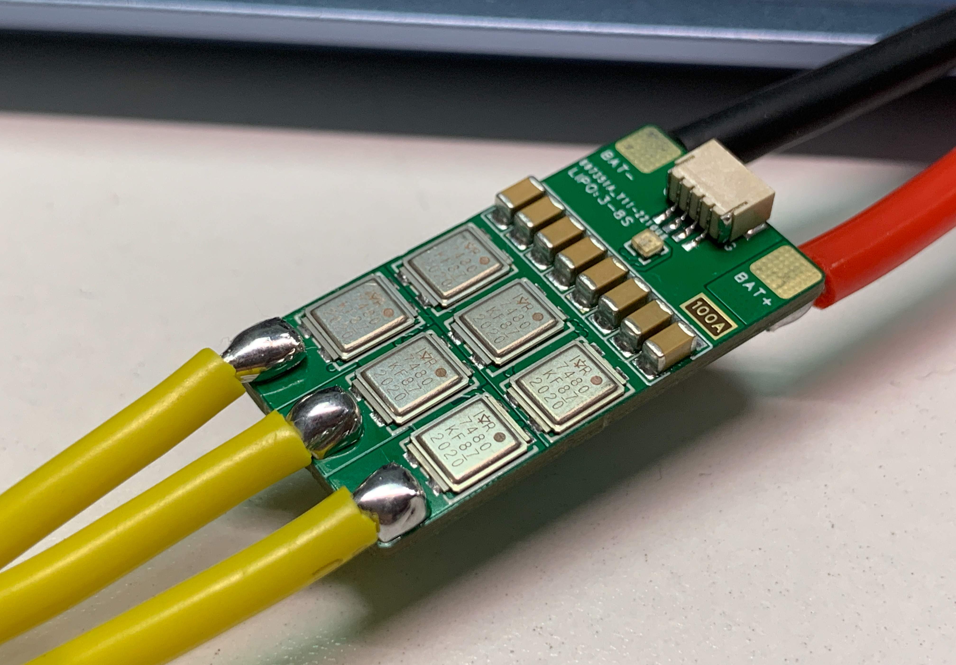
1. The main thing to pay attention to is the selection of high-voltage devices, the theoretical maximum withstand voltage of the ESC is 40V input, for the reserved margin, it is recommended to be 3~8S, and the TVS needs to be selected according to the input voltage to avoid the damage caused by the back electromotive force caused by the motor deceleration to the circuit, followed by the input filter capacitor needs to consider the withstand voltage capacity (including the input capacitance of DCDC), I chose a 50V MLCC capacitor.
2. The project is a six-layer board, in order to increase the overcurrent capacity of the ESC through the copper layer, it is possible that the 6-layer free proofing conditions are not met, resulting in the failure of the audit after the boarding, and the follow-up can not carry out the 6-layer free proofing.
3. The current detection conditions under the firmware belonging to Neutron are different from my design, which can be solved by compiling the firmware by myself, such as choosing to obtain the ESC data through the serial port, the voltage data is accurate, but the current data is selected by the flight controller for ADC sampling.
4. There is another PCB under this project for the use of heat sinks, it is recommended to be a 1MM aluminum substrate, if you need to use a thermal conductive silicone pad and cover a heat shrinkable tube for fixation, the surface of the Directfet MOS is conductive, and the surface of the Directfet MOS must not be directly touched with the aluminum substrate.
If you have any other production questions, please join the qq 479926321 and ask your questions in the group or contact the group owner directly.
Note: There is no reminder means for private messages on open source platforms, so it is easy to ignore private messages!
Designed by mtbsk8 (from OSHWHub)
Link:https://oshwhub.com/mtbsk8/ji-yu-am32-gu-jian-he-g071-de-32-wei-wu-shua-dian-ji-dian-diao-esc
Design Drawing
 Empty
Empty
Comment