

 Completed
[2023 Stars Project] Timing Dice
PRO [2023 Stars Project] Timing Dice
License
:GPL 3.0
Description
Project Origin
This project originated from a program I did a long time ago on UnboxThreapy, a famous unboxing blogger on Youtube. At that time, he unboxed a dice used for timing. It was in the shape of a hexagonal prism, and each side was marked with a different color. When the user puts the product upside down on the side corresponding to the number, it will start timing, and there will be a sound prompt when the timing is completed.
It is actually relatively simple to know its internal principles through its working method. What it mainly sells is an idea. But I have to say that it does simplify the scenes that require timing in daily life. It is a pretty good product, so I came up with the idea of replicating this product.
Before the project was established, I accidentally searched for this product on TB, and it turned out to be a product of a domestic company (but I don’t know if it was copied from abroad).

Introduction
As mentioned before, this work is a replica of a timing dice on the market. It is in the shape of a hexagonal prism with numbers on each side, representing the timing time. When the user turns the die upside down to the corresponding side, it will start timing, and there will be a sound prompt when the timing is completed.
In addition, in order to meet different needs, one of the six faces can be customized by the user. The user can set it through the two buttons on the front (top) of the hexagonal prism. The front screen will display the basic information of the system, and there will also be a corresponding animation to show the timing progress during timing.
Project Progress
- 2023.05 | Project Approval.
- 2023.08 | PCB board verification completed.
- 2023.08 | Shell design completed.
- 2023.10 | Integration testing completed.
Design Principles
(1) Principle Analysis
First of all, it can be seen from the function of this product that the hardware is relatively simple. An external circular screen is used for information display, and two buttons are used for user interaction. Internally, it needs an attitude sensor, which is the key to realizing timing when it flips. By identifying the angle of the product's flip, the timing time can be judged; there is also a buzzer for prompts. Of course, this product needs to be powered by a lithium battery, so it also needs a corresponding internal charge and discharge management circuit and power monitoring circuit.
(2) Scheme Design

When I was conceiving the product, I actually found that this product would require at least two boards to implement. My design is that the main board is at the bottom and the secondary board is at the top.
In terms of the choice of main control, this product does not require too many external devices, so it does not require too many pins; but for GUI, I choose the LVGL library, and for MPU6050, I plan to transplant the official DMP library. These two libraries are suitable for The consumption of memory and CPU computing power is particularly large, so you should choose the Cortex-M4 architecture and a large memory model, and finally choose the GD32F303CGT6 . This model from GigaDevice has a main frequency of 168MHz and 1024KB of RAM, which can fully meet the needs of this project. The key is that it is not expensive.
At first, I wanted to choose a domestic chip for the attitude sensor, but considering that the domestic ecosystem has not yet taken off, and the attitude fusion would have to be written by myself, I did not consider it; in contrast, the MPU6050 has enough routines for reference, and the official website also has a complete DMP library for pose fusion processing.
Because this product is powered by lithium batteries, it requires charge and discharge management. The classic TP4059 chip is selected, which can achieve a maximum charging current of 800mA; if you feel it is not fast enough, you can use TP4056, which can achieve a maximum charging current of 1A.
As for the screen, choose a round LCD screen. The driver chip is GC9A01 . It uses SPI for communication and has a resolution of 240x240.


Screen purchase link: https://item.taobao.com/item.htm?spm=a21n57.1.0.0.5f5f523cr8s2nu&id=684295016053&ns=1&abbucket=3#detail
(3) Hardware Design
1. Power Supply Part
Because it is powered by a lithium battery, it must only use LDO for voltage reduction. The chip is ME611C33M5G-N from Nanjing Weimob, with a maximum output current of 500mA.

Lithium battery charging and discharging management is more particular. My idea is that the lithium battery supplies power alone during normal operation. When the user plugs in the USB interface, the lithium battery supplies power to the board. The USB interface charges the lithium battery and also supplies power to the board. . So I designed the power supply switching circuit as follows.

The MOS tube in the picture is PMOS. When the USB interface (VBUS) is not input, the current of the battery (VBAT) can smoothly reach VIN; when the USB interface is connected, the MOS tube is turned off, and only the USB interface current reaches VIN at this time. There is a diode between VBUS and VIN to prevent VBAT from sinking current into VBUS; the voltage drop of the B5819W diode can usually reach more than 550mA, which is quite large for such a small voltage circuit. If you mind, you can replace it with SS14, the voltage drop is only Around 500mA, the parameters are the same except for the voltage drop, but the volume will be larger.
The lithium battery charging circuit can generally be drawn according to the data sheet. Select 1.5kΩ for the feedback resistor (PROG) to achieve the highest charging current of 800mA.

Battery power monitoring simply uses a series voltage divider to reduce the battery voltage by half, as long as the full voltage is less than the 3.3V of the microcontroller.

2. Main Control Part
The main control is generally designed according to the data sheet, but an external crystal oscillator must be added , because this product is a timer, and the timing will be accurate only if an external crystal oscillator is used. Also, the ADC power supply and ground are isolated with a 0Ω resistor, which can improve the anti-interference performance.

3. Attitude Sensor
The attitude sensor uses MPU6500 on the schematic diagram. In fact, it is not much different from MPU6050 except that it is cheaper. At the same time, a female header port that can be plugged into the MPU6050 is reserved. The reason for this design is because MPU6500 and MPU6050 are both QFN packages. It is extremely difficult to weld by hand. Therefore, if you cannot weld by hand, you can directly connect a ready-made module next to it.

4. Screen
The screen is fixed on the secondary board, so there is an FPC interface on the motherboard for connection. In the early stage, I found that if I want to use hardware SPI to communicate with the screen, I have to add a pull-up resistor , which is quite confusing. I also reserved a pin header for connecting to the screen, because the FPC socket is quite difficult to solder by hand.

5. User Buttons
The user buttons are also on the secondary board and are connected to the main board through FPC. The buttons are made of all-metal waterproof buttons, which are more durable. A bidirectional transient suppression diode is also added to the circuit to protect the circuit.

6. Buzzer
The buzzer I chose is active. After all, there is one less component to solder. I simply use a triode to control the switch.

Appearance Design
As for the exterior design, it's a little rough because this is my first time designing a casing and I don't have much experience in product design.
The original version uses an aluminum alloy + diffusion plate + plastic design, which is obviously a bit expensive. So I developed a pure 3D printing solution based on my own ideas.


Production Process
(1) PCB
PCB bare board.


Soldered PCB board.


Simply transplant an LVGL to verify it.

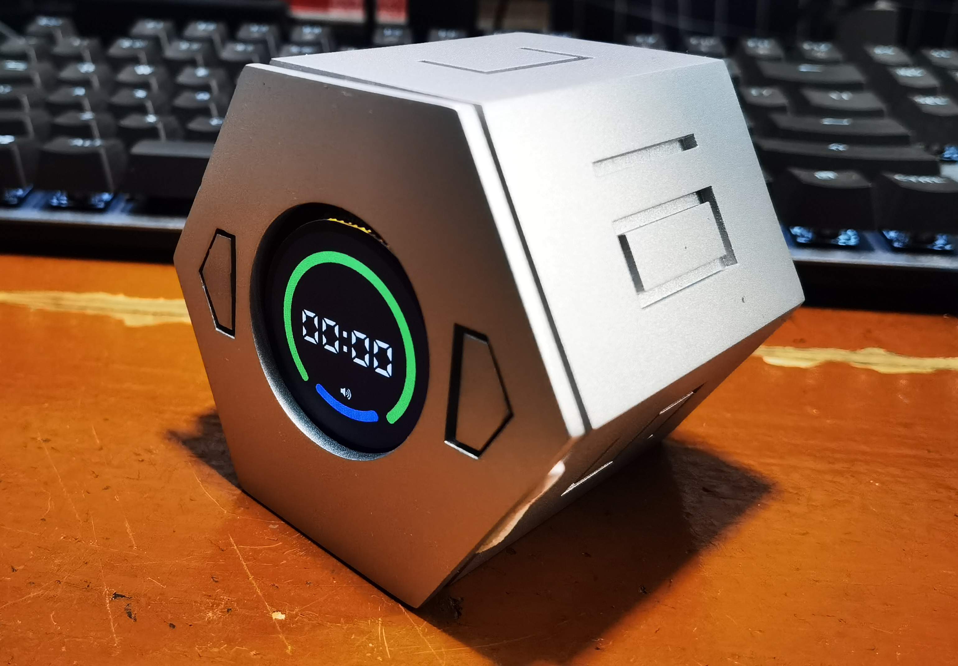
Actual picture after assembly.

Summarize
This Spark Project is the most challenging project I have ever done. From PCB design, case design, component welding, and coding, I have to do it all by myself. It is a challenge for a novice who has never designed a product. It was a huge difficulty, and obviously the finished product was not satisfactory either.
But after all, I learned a lot through this opportunity, and I hope we can continue our efforts in the next Spark Project.
Appendix
The project's firmware and 3D shell files have been open sourced and can be downloaded below.
Designed by jackiecoo (from OSHWHub)
Link:https://oshwhub.com/jackiecoo/xing-huo-ji-hua-ji-shi-tou-zi
Design Drawing
 Empty
Empty
Comment