

 Completed
Z21PG by DF PRO
PROZ21PG by DF PRO
License
:Public Domain
Description
Central Station Features
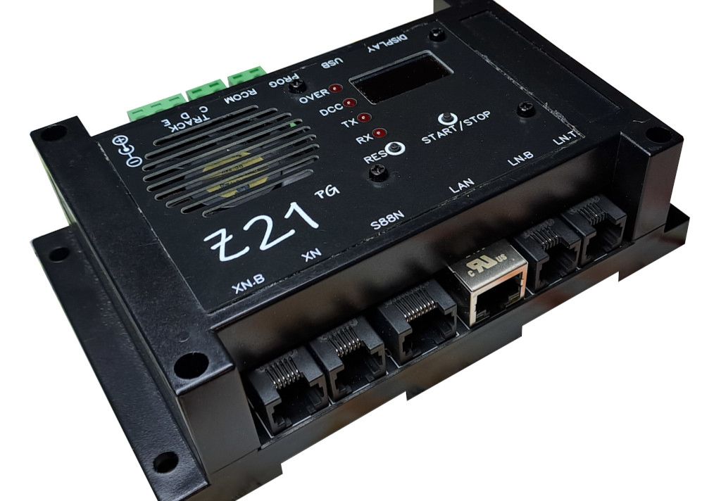
NMRA DCC central station, compatible with "black Z21" from Roco. Based on this design embeds all the functionalities and interfaces of a full featured station as open source platform. Hardware design available at JLCPCB, firmware available in Arduino platform.
- PC Ethernet (LAN) connection
- 2 x XpressNet ports (one "standard" for Lokmaus/MultiMaus connection, the second selectable "master or slave" for ROCO 10764 booster or LokMaus/MultiMaus connection)
- 2 x LocoNet ports (one "T type" for generic module like occupy detection circuits or throttles, the second "T type" for devices that needs DCC Railsync, for example boosters)
- 1 x S88N port for feedback module, up to 62 modules connectables
- 1 x USB port for firmware upload (Arduino bootloader) or debug
- Internal 3 Ampere booster, CDE output, short circuit protected with a threshold of 3.5A
- Programming track separate output and electronic switch between main and programming track
- RAILCOM detector with separate output for fast decoder CV readout
- FAN cooler with aluminium heatsink fastened to the PCB
- 1" OLED display for generic informations, 4 status/activity LED, 2 user buttons
- Temperature display with dedicated temperature sensor and fan activation over 45°C
- Display of supply voltage and current delivered to the track
Schematic Description
The electrical diagram is taken directly from that of Philipp Gahtow with some modifications to be able to be implemented and built through the JLCPCB website as a single board, without the need to purchase Arduino boards. Each section is identified with a box on the diagram for ease of reference.
The central part of the diagram is the heart of the control unit, the Microchip ATMEGA2560 microcontroller . The processor clock is 16MHz, the "reset" input is shown on the user panel to allow a restart of the control unit operations. Near the processor there is the J2 programming connector (2.54mm male header with 3x2 contacts) which is used for programming the microcontroller: I use this programmer , but there are many on the market and they are all fine for the purpose. At the ends of C32 the reference voltage (nominally 1.1 Volt) of the microcontroller can be measured (with a tester) and can be inserted into the Arduino code to improve the precision of A/D conversion of the supply voltage and current supplied.
The second section is the one relating to the Ethernet interface (LAN & WIFI). Also in this case, the part of the circuitry present on the Ethernet shield has been integrated (purified of everything that is not essential) in order to have the control unit on a single board. The interface is based on the Wiznet W5100 chip which implements all layers of LAN communication and connects to the microcontroller with a 4-wire SPI interface (MISO, MOSI, SS, SCK). The Ethernet interface clock is 25MHz and this chip is also reset together with the micro via a button on the user panel. The decoupling part from the bus (signal transformers) is integrated into the HR911105A (HANRUN) RJ45 connector which also contains two LEDs (green/amber) for displaying the link status. The receive and transmit LEDs are shown on the user panel (TXLED & RXLED). The WIFI part is based on an ESP-01 circuit mounted directly on the circuit and connected to the micro through a serial port: this part has not been implemented for now, I preferred to use the WIFI of the home router connected through the ethernet.
The third section is the one relating to driving the DCC signal towards the layout and towards the programming track. The driving of the track is achieved with the parallelization of 4 x Texas Instruments DRV8870 , each capable of delivering up to approximately 2 Amperes considering a board and heatsink temperature of 50°C. Considering a 50% derating for continuous use, the driving capacity will be approximately 4 Amperes towards the track (see proposed heatsink) through the TRACK - CDE connector). A fifth DRV8870 is used for the programming track only, which also has a separate output (PROG). To avoid using a mechanical relay, I implemented the switch between the programming track and the running track with a 74HC32 quadruple OR gate (remember that in the DRV8870 when the inputs are at a high logic level the outputs drive a low level). The Q7 MOSFET serves to have a 0.1 Ohm current sensing resistor during standard track operation and a 1 Ohm sensing resistor during programming track operations (for better detection of ACKnowledge from the decoder). The U12 photocoupler detects the short condition on the external booster (pin E) so as to signal it on the control unit and on any management software. In this section there is also the driver (Q9 mosfet) for the fan connected to the heat sink. The connectors towards the circuit are screw type, 5mm pitch, pins on the control panel and sockets on the cables, which can be detached from the control panel. The power supply voltage of the control unit is read through the R30/R31 divider.
The fourth section is the one relating to the power supply of the control unit. There are 3 DC/DC step-down converters for the different internal and external circuits. The first DC/DC converter ( TPS54331 by Texas Instruments ) creates a voltage of +12VDC with 3 Amperes of maximum current for powering the LocoNet and XpressNet bus. Each power output to these two buses is protected with self-resetting fuses. The second DC/DC ( RY8310 by RYCHIP Semiconductor ) converter creates a voltage of +5VDC, maximum 1 Ampere which powers all the logic integrated circuits of the control unit. The third DC/DC converter ( RY8310 by RYCHIP Semiconductor ) creates a voltage of +3.3VDC, maximum 1 Ampere which powers all the "low power" logical integrated circuits of the control unit such as the Ethernet interface. These DC/DC converters have a maximum input voltage of 28VDC and 30VDC respectively, the power connector is of the tube type with 5.5mm external and 2.5mm internal, with the positive on the internal part.
The fifth section is the one relating to the RAILCOM receiver connected to a specific output of the control unit (RCOM) which will therefore allow the bidirectional exchange of information with the decoder (in practice a faster way of reading the CVs) without using the programming track. The RAILCOM receiver is based on a Texas Instruments LM293 dual comparator that compares the 30mA current loop drop across a 1 Ohm resistor with a threshold taken from a resistive divider. There are two comparators so the RAILCOM current can flow in both directions, depending on how the loco is positioned on the track.
The sixth section is the one relating to the interface with the LocoNet bus. There are two connectors, LN.T(hrottle) type RJ4, standard for any use powered by +12VDC and LN.B(ooster) type RJ5 powered with the DCC signal amplified by a Microchip TC4428 power driver and with a resistor 22 Ohm output on each line as per LocoNet standard. The 15mA active pull-up for the Loconet bus can be deactivated via jumper H1 if another pull-up is already present on the bus.
The seventh section is the one relating to the S88 interface. It is implemented through a Nexperia 74HC245 buffer for transmission on long lines and implements 50 Ohm resistors in series with the bus signals to minimize signal reflections. Up to 62 S88 modules can be connected in series (the exact number can be selected from the web interface), the interface standard is the S88N on an 8p8c RJ45 connector.
The eighth section is the one relating to the XpressNet interface. There are two between pins 2 and 3. In the "master" position the power supply for the pull-ups of the DCC and GO/STOP signals comes from the booster and on connector pins 1 and 6 there are the DCC signal and the short circuit signal. The circuit in "master" configuration is necessary to connect Roco 10761/10764 boosteers and similar. The RS485 transceiver is implemented with an EXAR SP485EEN integrated circuit .
The ninth and final section is the one relating to the auxiliary interfaces present in the control unit. The Mysentech MY18B20Z chip is a circuit compatible with the DALLAS DS18B20 thermometer for reading the temperature near the power elements and for being able to activate the cooling fan in case of too high temperatures. The USB interface is implemented with the WCH CH340N integrated circuit . The connector to the user panel (which can be either in the control unit box or externally, for example on a separate control panel) is based on a 12-pole JST ZH connector (1.5mm pitch) and carries the signals for the control LED. OVERCURRENT, the DCC presence LED, the two TX and RX LEDs of the LAN interface, the 1 inch OLED display and for the two control unit RESET and START/STOP buttons of the DCC signal.
The diagram of the display panel is very simple and is based on 4 red LEDs (OVER, DCC, TX and RX), two normally open buttons (RESET and START/STOP) and an OLED display based on the SSD1306 controller .
PCB accomodation
The main changes to the project were made to allow for a single PCB, compatible with a low-cost plastic box that could be found on the market without difficulty. The budget for the entire control unit shall be under €100 and to achieve this goal I studied this basic architecture:

- the wiring diagrams of the "Arduino Mega" board and its "Ethernet Shield" have been reduced to a minimum of the necessary components and integrated into a single board
- The relay (main / programming track) has been removed and replaced with a logical switch (74HC32)
- The power parts have been replaced with SMD parts and dissipated with integrated fan + cooling fin with activation of the wind above a limit temperature (45°C)
- The XpressNet and LocoNet ports have been doubled to allow you to have both "master" and "slave" for the XpressNet and both "LocoNet T" and "LocoNet B" for the Loconet.
- The section monitored with RAILCOM was separated from the main track because the 0.1 Ohm sensing resistors are too small for reliable detection of the current loop and the 1 Ohm ones are too large to pass all the current of the layout through.
- The user panel has been separated to allow it to be released from the control unit box and fixed to a remote control panel.
- All the power supply voltages were generated with DC/DC converters to reduce the dissipated power and improve the efficiency of the entire system
- The components with the best quality/price ratio were chosen, where possible.
Project source code
- Unzip this package into the /Z21 directory in your PC (original files). Install in Arduino all the required libraries.
- Take note of the path for the Arduino Libraries in your PC ("Arduino Libraries path")
- Download this package (modified files) and substitute/overwrite the following files:
- Copy the modified file "config.h" for the Z21PG by DF central station overwriting the "\Z21\Z21_Ethernet_DCC_Zentrale_v498\config.h" original file
- Copy the modified file "POWER.h" for the Z21PG by DF central station overwriting the "\Z21\Z21_Ethernet_DCC_Zentrale_v498\POWER.h" original file
- Copy the modified file "Z21_LAN.h" for the Z21PG by DF central station overwriting the "\Z21\Z21_Ethernet_DCC_Zentrale_v498\Z21_LAN.h" original file
- Copy the modified file "Z21_Ethernet_DCC_Zentrale_v498.ino" for the Z21PG by DF central station overwriting the "\Z21\Z21_Ethernet_DCC_Zentrale_v498\Z21_Ethernet_DCC_Zentrale_v498.ino" original file
- Copy the modified file "DCCHardware.cpp" for the Z21PG by DF central station overwriting the "Arduino Libraries path\Z21\DCCInterfaceMaster\DCCHardware.cpp" original file
- Copy the modified file "DCCHardware_config.h" for the Z21PG by DF central station overwriting the "Arduino Libraries path\Z21\DCCInterfaceMaster\DCCHardware_config.h" original file
Compile the sketch and flash it within the ATMEGA2560 microcontroller.
Project assembly
See project attachments section.
Videos
Z21PG & Z21 APP: CV read & write
Z21PG & Z21 APP: decoder control
Design Drawing
BOM
 Clone
CloneProject Members
 Empty
Empty
Comment