

 Ongoing
Smoke Detector with Arduino
STDSmoke Detector with Arduino
License
:Public Domain
Description
In many homes, accidents with cooking gas occur because people forget to close the valve. The gas leaks and can generate two major accidents: explosion or death by aspiration in large quantities during sleep.
One of the ways to avoid this is through a gas presence monitoring system. This is done through the use of sensors.
In this article we will build a system to monitor the presence of cooking gas. We will develop an electronic control board and an enclosure to store the circuit structure. See some images of this project.

The 3D enclosure design was developed with JLC3D. The entire structure was designed to be manufactured with the resin material to obtain a better finish and surface quality of the structure.
This enclosure costs approximately $6.50. However, JLC3D offers a $5 discount coupon for you to print this or another project. Use the JLC3D coupon and receive the 3D enclosure in your home.
Download all project files through this link.
Below we will explain the complete development of the project.
Flammable Gas and Smoke monitor development
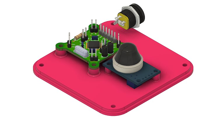
The following structure represents the electronics that were the gas sensor:
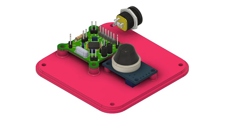
As you can see, you will use 4 electronic elements:
- Control board with ATMEGA328P-AU CHIP;
- MQ-2 Gas Sensor;
- Female Jack connector for 9V power supply;
- Enclosure.
The project is divided into two parts: the electronic structure and the enclosure. Next, we will see the operation of the electronic circuit.
Project Electronic Circuit
We developed an electronic board with an ATMEGA328P-AU CHIP. This circuit was developed to facilitate development and testing for several prototypes that use few digital inputs and outputs and occupy a small space. Below we have the structure of the electronic board.
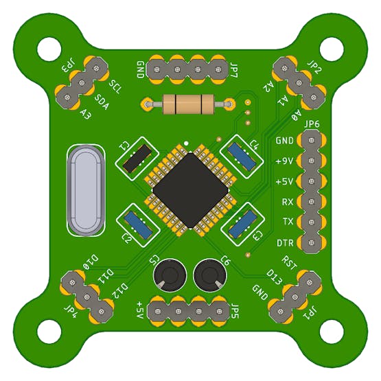
The electronic board has pins for in-circuit recording (+5V, GND, TX, RX and DTR). In addition to them, we put access to other digital and I2C pins. The latter allow, for example, the use of an LCD with I2C.
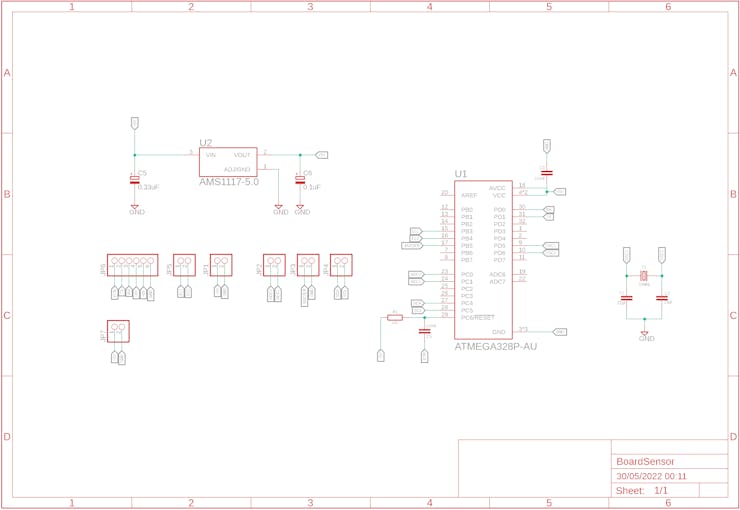
Below we have the complete schematic of the electronic circuit.
The electronic design of this board is available for download. You can download and win 5 free JLCPCB units. To do this, just follow the steps below.
- Access this link and create an account on the JLCPCB website;
- Upload the Gerbers files on this website;
- Apply the JLC-REBE coupon on the payment page to get 5 free units.
- This video explains the step-by-step process for ordering electronic boards.
The board with the ATMEGA328P is designed to receive the connection of the MQ-2 sensor and the buzzer.
The MQ-2 sensor is responsible for reading the environment and detecting possible particles of butane gas. This sensor is powered with 5V and has two forms of signals: one analog and one digital.
See its structure in the figure below.
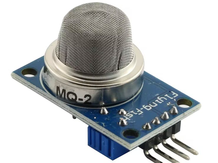
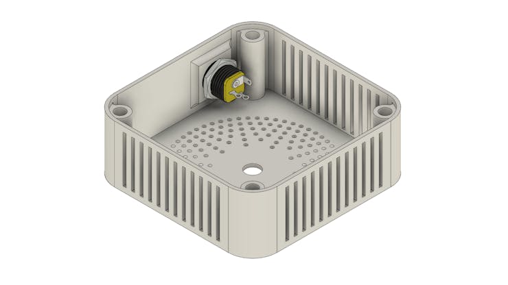
The sensor is installed in the internal structure of the enclosure.
In addition to the sensor and the electronic board, we have a Jack connector to facilitate powering the internal circuit.
Next, we have the enclosure structure developed for the project.
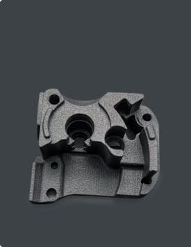
3D Development of the Project Enclosure
Enclosure was developed to facilitate the installation of the electronic circuit and to better present the quality of the prototype.
The prototype structure was developed with several holes in the upper region and cuts in the lateral regions. This facilitates the entry of gas into the sensor region.
The enclosure structure is divided into two parts: top cover and base.
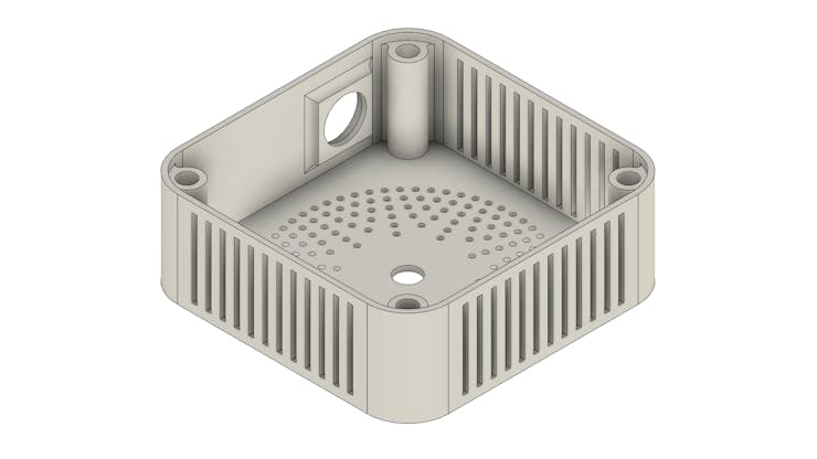
Below is the base figure.
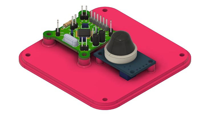
It has all the holes for fixing the electronic control board and the sensor. In addition to the fixing holes for the plates, we have 4 holes at the ends fixing the base with the cover. See the figure below.

The base frame has a fifth hole to allow the user to adjust the sensitivity of the sensor.
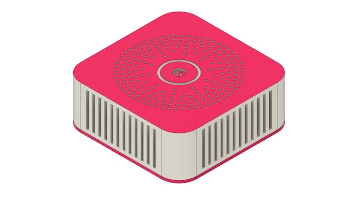
Finally, we have the enclosure lid. As already mentioned, its structure has several cuts to facilitate the entry of gas into the internal region of the circuit. See the figure below.
The internal structure of the lid has 4 holes. Insert nuts will be installed in each hole to allow the fixing of the base screws. The figure below shows the side view of the internal structure of each hole.
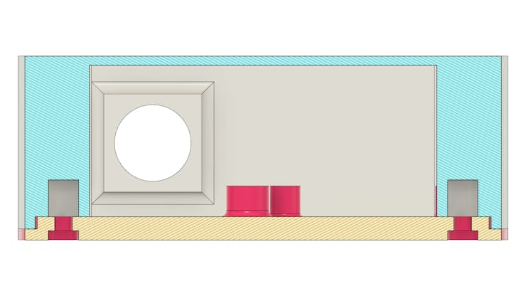
The front hole shown in the figure above was created for fixing the Jack connector. This connector is used for external power with a 9V supply. See the figure below.
Now we will talk about the structure of programming logic for gas monitoring.
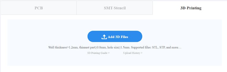
How to produce 3D Enclosure with JLC3D
Firstly, you need access the JLC3D Website through this link and click in Add 3D files button to upload each file of your project.
After, all files will be presented and you need to select 3D Techonology, Material and other parameters to produce your 3D print project.

This project, for example, was selected to be produced with SLA Technology, LEDO 6060 Resin, Natural White color and will be produced in 48 hours.
The total to produce two pieces will be an amount of $6.26. It's very cheap!
Enjoy and access JLC3D to create any prototype!
Now, we'll understand the programming logic of the project.
Development of programming logic
The programming logic for the project consists of reading the sensor and monitoring the level of gas present in the environment. If this value exceeds a defined threshold, then the system will trigger a buzzer to alert users.
There are two ways to perform the sensor reading. The first is through reading the analog signal, and the second is through the digital output. In this second option, we must adjust the threshold through the potentiometer. Whenever the analog signal exceeds the set value, then the digital output will be at 5V. Otherwise, the output will have the value 0V.
In this project we will use the digital output of the MQ-2 sensor. Next, we will present the project control code.
void setup()
{

pinMode(12, INPUT);
pinMode(13, OUTPUT);

}

void loop()
{

sensor = digitalRead(12);

if(sensor == 0)
{
   digitalWrite(13, HIGH);

}

if(sensor == 1)
{
   digitalWrite(13, LOW);
}

}
The code is very simple. The Arduino will read the digital input that the sensor is connected to. If the amount of gas/smoke is above the value configured in the sensor trimpot, then the sensor output will be high logic level (5V). In this situation, the Arduino will activate the output (D12) and trigger the buzzer.
Otherwise, the Buzzer will be turned off.
See some images of the structure that was printed.

The enclosure is available for download and you can download it and use it in different electronic projects.
Go to this link and download all the files.
Conclusions
The above project was developed and is available to be applied for the study and development of electronic projects with the MQ-2 sensor.
The Enclosure has internal dimensions of 62 mm x 62 mm and can be used in numerous electronic projects. Soon we will present the result of this case printed in resin with the JLC3D and we will make a comparison with the FDM technology.
Thanks to JLC3D for providing free samples of enclosure for further testing. Access JLC3D and use the $5 discount coupon JLC3D.
Design Drawing
BOM
 Clone
CloneProject Members
Intellectual Property Statement & Reproduction Instructions
This is an open-source hardware project. All intellectual property rights belong to the creator. The project is shared on the platform for learning, communication, and research only; any commercial use is prohibited. If your intellectual property rights are infringed on EasyEDA, please notify us by submitting relevant materials in accordance with the Rules for Complaints and Appeals of IPR Infringement.
Users must independently verify the circuit design and suitability when replicating this project. All risks and consequences are borne by the user, and the platform assumes no liability.
 Empty
Empty
Comment