

 Ongoing
Electronic Feeder for Pets with Arduino
STDElectronic Feeder for Pets with Arduino
License
:Public Domain
Description
The following project is a 3D printed fish feeder. All files are available for download and you can access the files to manufacture them at JLC3D, one of the largest manufacturers of low cost 3D printed parts in China. See some pictures of this project.
Want access to the STL files right now? Click on that link and I will send the files to you via WhatsApp. In addition, JLC3D offers the JLC3D discount coupon with $5 off for you to use on your purchases. Use JLC3D coupon now!
You can print your part with 5 different technologies on JLC3D. See some pictures of parts printed in each techonology used by JLC3D.
The following project was developed with FDM Technology (Fused Deposition Modelin). Now let's learn how to assemble the electronic fish feeder.
Electronic Feeder for Small Animals
Many people who raise pets spend hours outside the house and often the food runs out or they forget to put food for them. This can harm the health of your pets or they can die from lack of adequate food.
One way to avoid this problem and leave an automatic feeding for your pet is through an electronic feeder. Through this device your pet will receive several daily portions of food and you will be carefree throughout the day.
That's why we've developed an electronic feeder for you. It can be used for different types of pets that use food in the form of bran and small grains of feed.
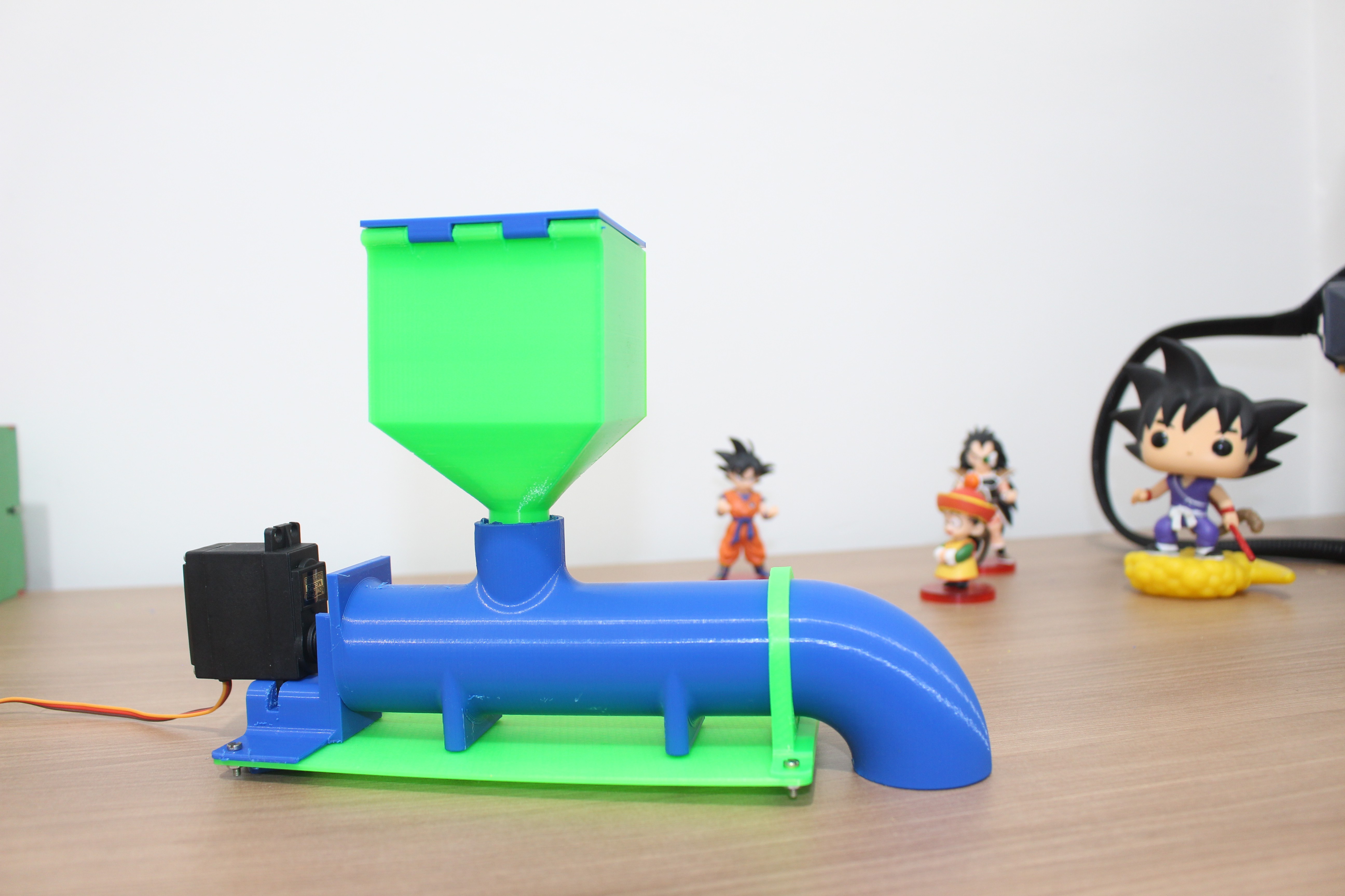
The structure of the feeder is presented below and below we will discuss each part of its operation.

The structure of the electronic feeder is formed by the following parts:
- food reservoir,
- pipe,
- Rotation system with servomotor and Archimedes screw, and
- Structure fixing base.
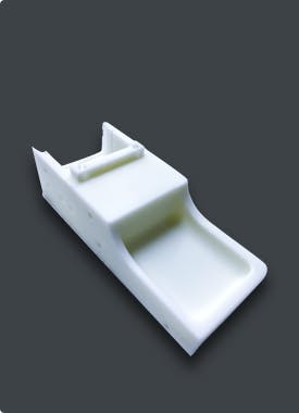
The reservoir is used to store the food. See the structure in the figure below.
The reservoir has a lid to protect the feed. Its structure must be directly coupled to the pipe to release the feed to the pet. See the figure below.

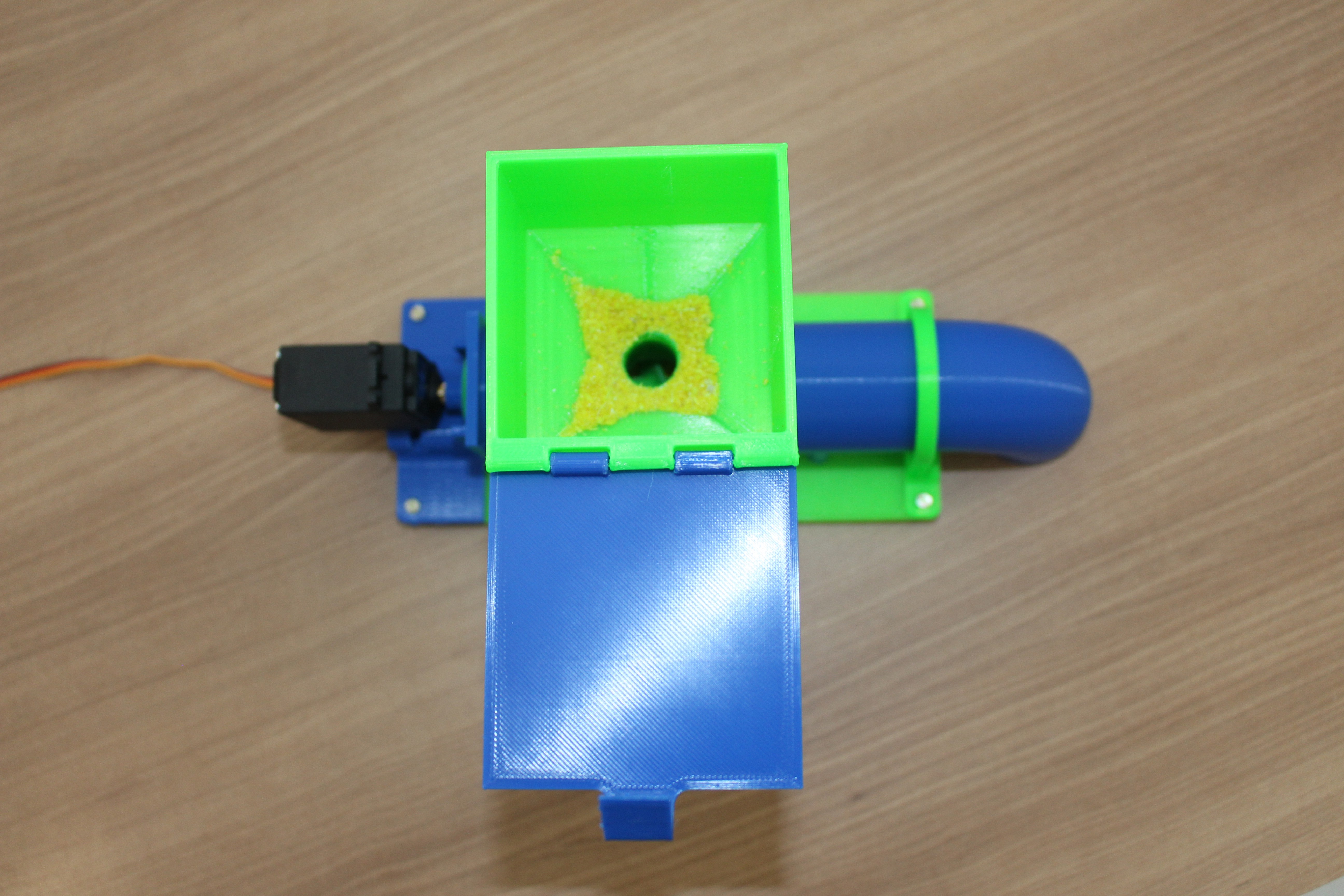
The pipeline is shown below. Its main function is to act as a guide to take the food to the pet's food bowl.

Inside the pipe we have the element that is responsible for transmitting the feed to the pipe outlet. This element is an Archimedean screw. See its structure in figure below.

Our Archimedes screw is designed to be attached to the shaft of an MG995 servomotor. This servo has a high torque and has control of speed and direction of rotation through the Arduino PWM signal.
What is the Archimedes screw and how does it work? We will talk about its working principle in the next topic.
The working principle of the Archimedes Screw
Archimedes' screw is a very old invention and used by several civilizations to transport water in irrigation systems.
The video below presents the use of the mechanism by ancient civilizations.
The screw was manually moved to transport water from one level to another.
Over the years, the mechanism has been improved and engines are now used to move it. In addition to transporting liquid, the system allows transport of solids.
Watch the video below and observe the transport of solids.
This is how all small feed grains and meal will be transported within the pipeline structure.
Now, see the support structure used for fixing the mechanical assembly of the servomotor and Archimedes screw.
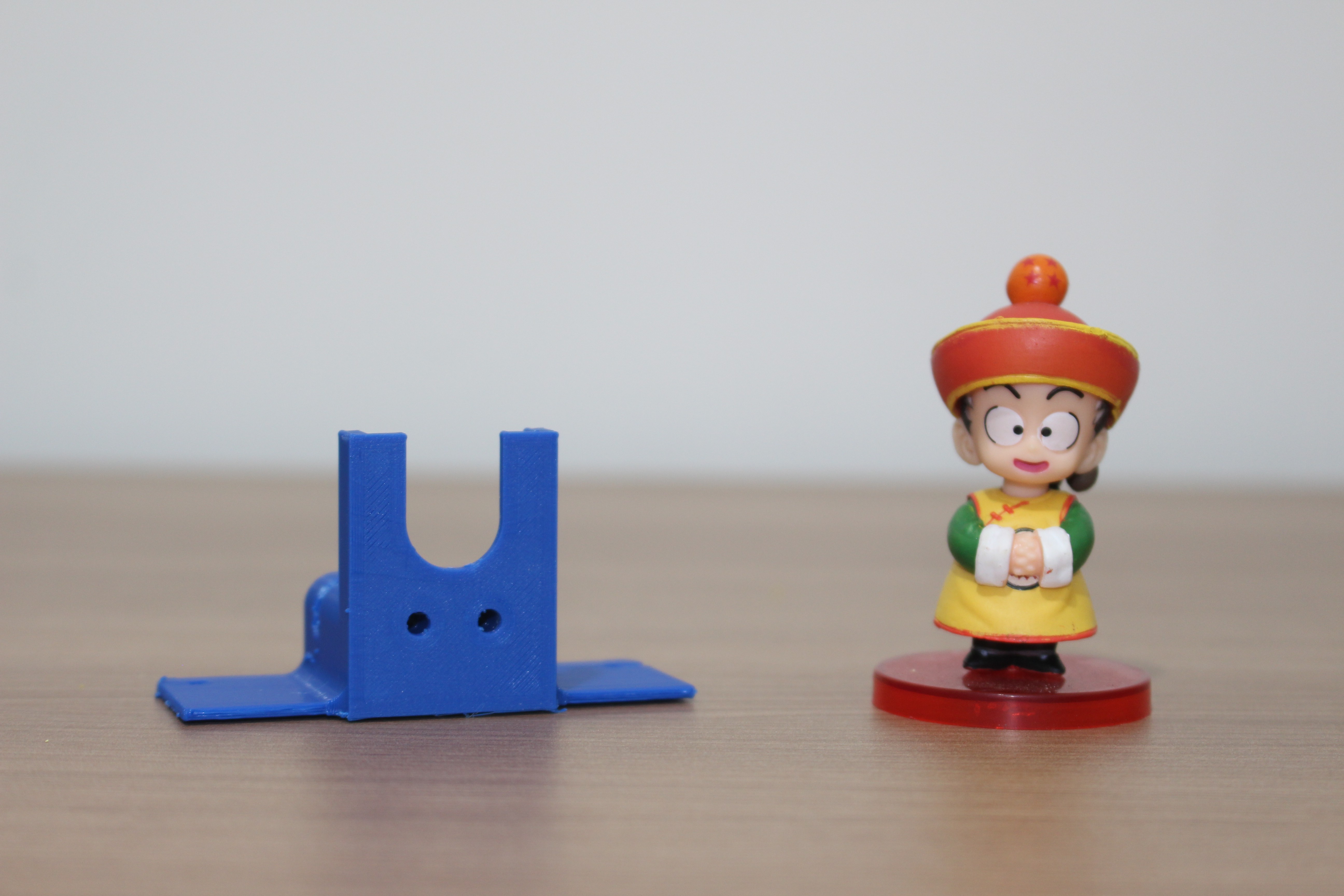
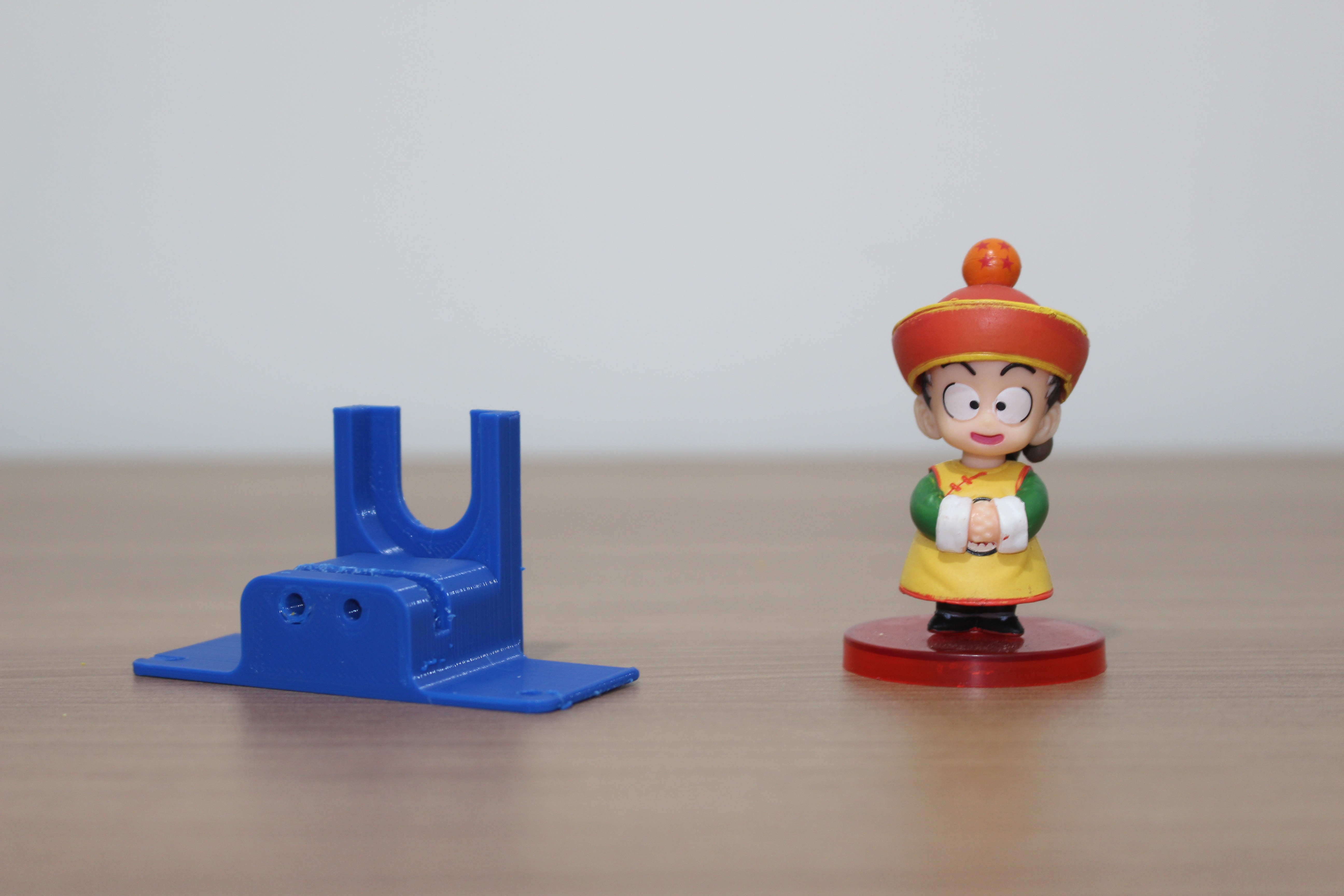
The two holes are used to fix the motor through bolt and nut.
The figure below shows the motor and the screw installed in the frame of the support part.
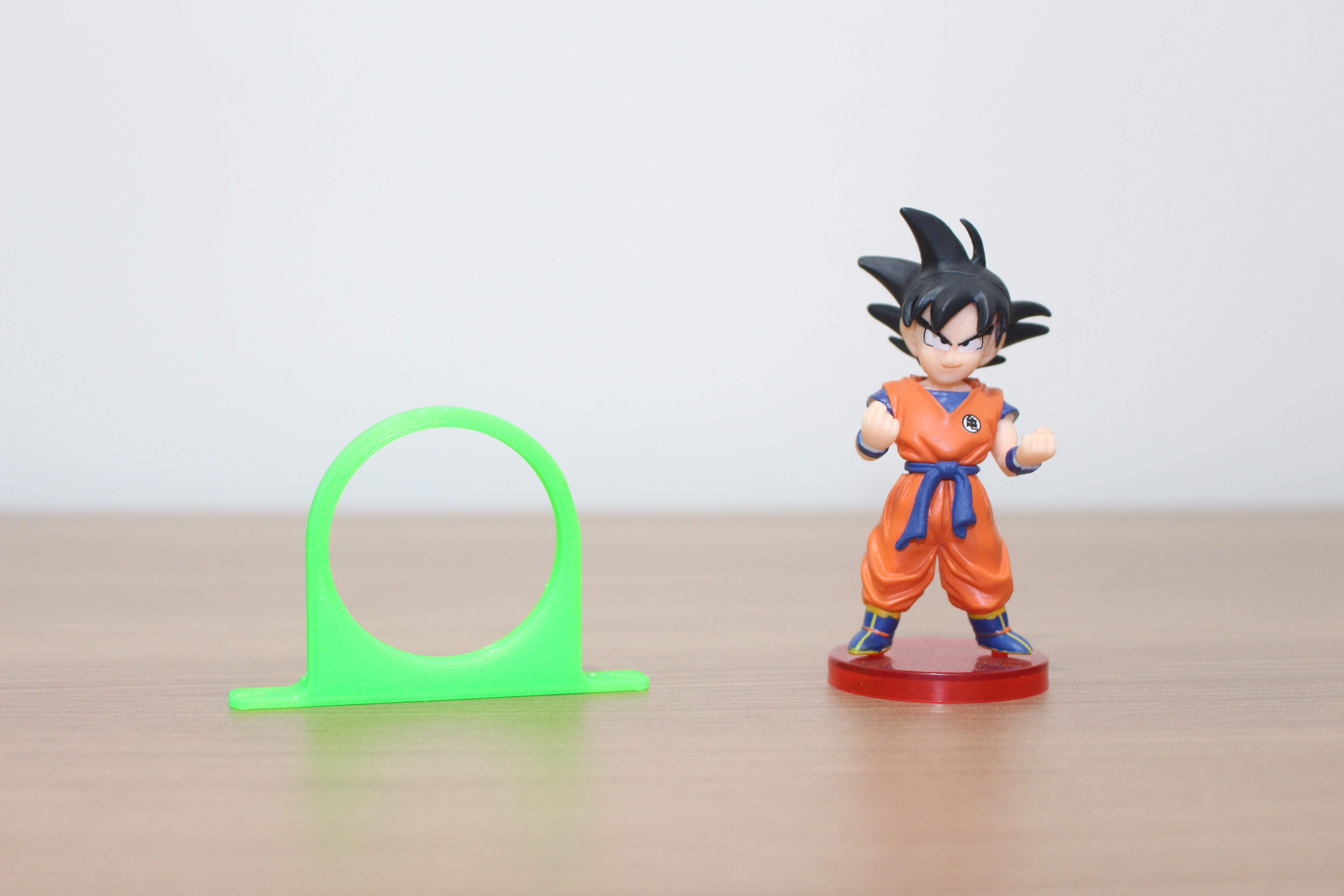
To facilitate the installation of all parts and reduce vibration, a support base was created, as shown in the figure below.

Two parts will be mounted on this base, the engine support part and the part to support the pipe outlet.
After assembly we have the complete system and ready to feed your pet.

From this structure you can create several projects and programming logic to control the periods of food release for your pet.
Below we will leave some suggestions of applications for you to create and control your pet feeder.
Control Program Suggestions for the Pet Feeder
The first suggestion we have is to create a program with Arduino to release food to your pet every 4 hours. For this project you will need the following electronic components below.
These are the 3 main electronic elements to build this idea. The Arduino will be responsible for executing the control of the programming logic and reading the time provided by the real-time clock.
Every 4 hours the Arduino must activate the MG995 servomotor for 3 seconds to release the food to your pet. This time can be adjusted in the project control program.
The code below is the solution to this problem. From there you can change and create new ideas.
#include "Servo.h"
#include <DS1307.h>
#include <Wire.h> //Biblioteca de Comunicacao I2C int DataTime[7];int actual_hour = 0, last_hour = 0;int cont = 0;Servo myservo;void setup() {    Wire.begin(); //Inicializacao da Comunicacao I2CDS1307.begin();DS1307.getDate(DataTime);actual_hour = DataTime[4];last_hour = DataTime[4];myservo.attach(9);}void loop() {  DS1307.getDate(DataTime);  actual_hour = DataTime[4];  if(actual_hour != last_hour)  {    cont++;    last_hour = actual_hour;    }  if(cont == 4)  {    myservo.write(180);      delay(30000);    myservo.write(90);    cont = 0;    last_hour = actual_hour;     }  }
Do you want to build this project with Arduino quickly and with a less complex circuit? We developed the Arduino Shield PCB to facilitate the construction of any project with Arduino UNO.
Shield can facilitate the assembly process for your entire project. Find out why!
You can apply it to any project with Arduino UNO.
It is available for download, and you can earn 5 units for free at JLCPCB.Follow the step by step and get the shield right now in your home! It's free!
You must follow all these steps below.
- Download the robot control board file
- Enter on this website and make your account.
- Add the control board files to the website
- Add the JLC-REBE discount coupon to the payment section
- Ready, you won 5 free PCB units.
Also, you can download the STL files of that project.
Download the STL Files and print your project with JLC3D
The structure of the electronic feeder is composed of 8 pieces. Do you want to have access to all files and print them with JLC3D?

Send an email to fcodiegomoreira@gmail.com or contact me on WhatsApp: https://wa.me/+5585999831612
Acknowledgments
Thanks to JLC3D for providing free samples of enclosure for further testing. Access JLC3D and use the $5 discount coupon JLC3D.
Design Drawing
BOM
 Clone
CloneProject Members
 Empty
Empty
Comment