

 Completed
Adjustable_PSU
PROAdjustable_PSU
License
:MIT License
Description
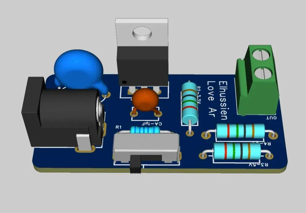
DIY Selectable Voltage Power Supply
Power your electronics projects with confidence using this versatile DIY power supply unit. Built around the reliable LM317 adjustable regulator, this board delivers three of the most commonly used voltages for hobby electronics: 5.1V, 9V, and a high-power setting. A simple, robust slide switch lets you instantly select your desired output. Designed for clarity and ease of assembly, this project is ideal for any hobbyist seeking to build a core component of their electronics workbench.
Tips for New Features
1. Add LED Indicators for Each Voltage
To see which voltage is selected, you can add an LED that lights up for each switch position.
-
How it Works: For each of the three voltage-setting resistors (
750Ω,1.5kΩ,2kΩYou will add a separate LED and its own current-limiting resistor in parallel. -
Circuit Connection:
-
Connect a 470Ω resistor in series with a standard LED (e.g., a red one).
-
Connect this resistor-LED pair in parallel with your
750Ωresistor (across the same two points). -
Repeat this process with a new resistor and LED for the
1.5kΩpath (maybe use a green LED) and the2kΩpath (a blue LED).
-
Now, when you slide the switch to the 5V position, it will activate the 750Ω resistor path, and the red LED will light up. When you switch to the 9V position, the green LED will light up, and so on.
2. Protect the Slide Switch
When you move a slide switch, there is a brief moment when it is not touching any contact. During this split second, the LM317's Adjust pin becomes disconnected ("floating"), which can cause the output voltage to spike to its maximum. This can damage sensitive components.
-
The Solution: Add a single, large "protection resistor" to ensure the Adjust pin is never floating.
-
Circuit Connection: Connect a 10kΩ resistor directly between the Adjust pin (Pin 1) of the LM317 and Ground.
This resistor's value is high enough that it won't significantly affect your normal voltage calculations. Still, it's low enough to keep the Adjust pin grounded during switching, preventing the voltage spike.
Design Drawing
BOM
 Clone
CloneProject Members
 Empty
Empty
Comment