 Ongoing
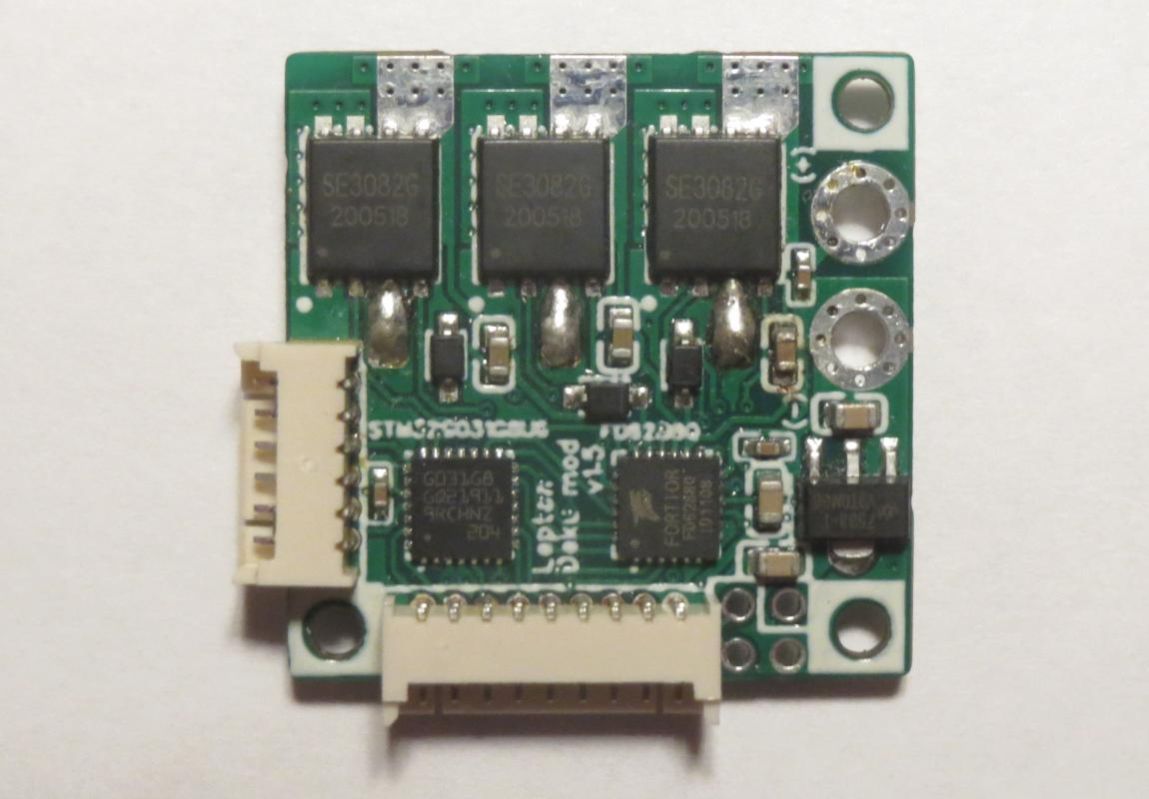
Lepton Deku mod BLDC SimpleFOC Driver
STDLepton Deku mod BLDC SimpleFOC Driver
License
:CERN Open Hardware License
Description
https://oshwlab.com/cost.co/20220903_bldc_se3082g
https://community.simplefoc.com/t/lepton-v2-revised-design-tested-working-30v-80a-mosfets/2489
DISCLAIMER: I am a monkey and I have no idea what I'm doing.
Changes:
1) Size reduced from 30x40mm to 25x25mm
2) Exposed copper along + and - rails on back of board, so heavier conductors can be added
3) Changed motor wire holes to solder pads, to reduce size and so the wires connect directly to the MOSFET pins.
4) Removed the 5 ceramic capacitors from upper right (I will hand solder up to 12 of them on the back side instead, or just use a larger electrolytic)
5) Reworked the connectors (see note 1)
6) Removed the 12V buck converter (see note 2)
7) Removed the reset button (reset pin is still accessible via the programming connector)
8) Changed UART_RX from pin 22 to pin 8 to help with routing.
9) Replaced the 22uF 1206 capacitor with two 10uF 0603, and replaced the lower voltage 22uF 0603 with 10uF to reduce unique part count and because it's what the LDO datasheet recommends.
Note 1: There is now one 9 pin 1.25mm pitch connecter used during programming, one 6 pin for the encoder, and four 2mm pitch holes/pins for power and I2C communication in final application. The connectors are right-angle type, to allow stacking boards to save space and share a single cooling fan, and the power and communication wires can be passed axially through the stack.
The encoder connector is designed so you can use an SPI encoder, 3 digital hall sensors, or 2 linear hall sensors as described here https://community.simplefoc.com/t/40-cent-magnetic-angle-sensing-technique/1959
However the digital halls need higher than 3.3V power while other encoders need lower than 12V, so I had to add a solder jumper to select which voltage rail to connect to the power pin.
Note 2: My primary reason for removing the buck converter is that I will be running 8 motors on 3 cell lipo, so that would be a lot of wasted space and components when I can use the main voltage directly. There are several options for the mid-voltage power now, so I renamed it to VCC instead of 12V. The gate driver chip can use 5V to 20V, and the 3.3V regulator may overheat above 12V, so 5V to 12V is the usable range. Higher is better because the MOSFETs need 10V to fully open (5mOhm, versus 7.5mOhm at 4.5V), but it is nice that the 5V from standard radio control equipment, Arduino or USB can be used, or 7.4V from 2 cell lipo.
Design Drawing
 The preview image was not generated, please save it again in the editor.
BOM
 Bom empty
 Clone
CloneProject Members
 Empty
Empty


Comment