

 Ongoing
Drive Base for autonomous robot
License
:MIT License
Description
Project introduction and function
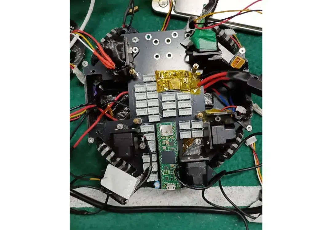
This custom-designed PCB is built around the Teensy 4.1 microcontroller, providing a versatile platform for controlling motor drivers, processing lidar data, and interfacing with a gyroscope. It integrates dedicated circuitry and power regulation to support high-current motor drivers, while maintaining precise timing and low-noise signal processing essential for lidar and inertial sensor applications. The board’s layout ensures optimal signal integrity and minimizes electromagnetic interference, making it ideal for robotics and autonomous systems where reliable sensor feedback and motor control are critical. The components used are also all Commercial Off The Shelf parts. Hence the you are able to easily replicate this project at home as well.
Principle analysis (Hardware description)
The project works on integrating the different sensors to get a better and more accurate sensing of the location of the product. Through fusing the data from the lidars, pointing in all 4 cardinal directions, as well as the gyroscope, the teensy is able to process the information and produce a location of the board in its relative space. This works better for systems that are in a confined area/an area of known dimensions, but unknown location within this area. The traces are hand routed to avoid having long traces, as well as have traces overlap in non-perpendicular angles.
Software code
For the camera used in this project, the OpenMV software is used to detect objects. Objects to be detected are of normal colours (e.g. blue, yellow etc). Software will have colour detection using threshold RBG values. Do note that when you are using your own OpenMV, the colour values you use may vary depending on the lighting of the area.
Localisation is based off sensor-fusion, using the Lidars and Gyroscope with different weightages in the algorithm. The lidar readings were used for a particle filter algorithm where the "particles" represent possible positions of the robot in the known area.
Bill of Materials
| Item | Quantity | Comment + Link to datasheet |
| Teensy 4.1 | 1 | https://www.pjrc.com/store/teensy41.html |
| TFmini Plus Lidar Module | 5 |
One for each cardinal direction + one redundancy https://cdn.sparkfun.com/assets/2/b/0/3/8/TFmini_Plus-01-A02-Datasheet_EN.pdf |
| BNO085 | 1 |
Gyroscope for system |
| 50A Dual-Channel motor drive module | 4 |
Motor driver, dual-channel for four motors. https://www.elechouse.com/product/50a-dual-channel-motor-drive-module-arduino-compatible/ Download link for Arduino Library: https://www.elechouse.com/elechouse/images/product/50a%20high%20power%20motor%20driver/50a%20motor%20driver%20code%20for%20arduino.rar |
| Mini560 (MINI DC-DC step-down module) | 1 |
Step-down Buck regulator |
| OpenMV H7 | 1 |
Camera https://mm.digikey.com/Volume0/opasdata/d220001/medias/docus/2098/SEN-14186_Web.pdf |
Assembling process
1. All of the ports of the jsts are labelled with their respective pin number. Solder jst headers (female) as required by your project.
2. Make the connector to wire (male) connectors from your components to the female jst port on the board.
3. Ensure that the parts run using sample code from the developer of that part/arduino to easily code and test the component.
Design Drawing
BOM
 Clone
CloneProject Members
 Empty
Empty
Comment