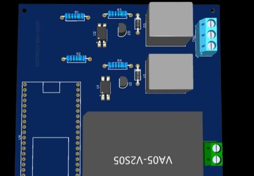
 Ongoing
16-channel-ir-array
STD16-channel-ir-array
License
:Public Domain
Description
16 channel ir array module
Design a **16-channel infrared (IR) sensor array** for detecting the proximity or presence of objects in front of each individual sensor in real time. The array will be used in applications such as object detection, surface following, or line tracking for a mobile robot. Each of the 16 IR sensors should independently detect objects and provide data regarding the distance or proximity of an object in front of it.
Key requirements:
1. **Sensor layout**: The sensors should be evenly distributed across the array to maximize coverage. Each sensor should detect objects within a defined range (e.g., 5 cm to 50 cm).
2. **Data output**: The array should output the proximity data for all 16 channels simultaneously. This could be done via analog or digital outputs, depending on sensor type and configuration.
3. **Integration with microcontroller**: The data should be easily readable by a microcontroller, such as an Arduino, ESP32, or a similar platform. The array should communicate using a simple protocol, like I2C, SPI, or parallel output.
4. **Power requirements**: The array should operate within a low voltage range (e.g., 3.3V or 5V) and consume minimal power to ensure efficiency for battery-powered systems.
5. **Accuracy**: The IR sensors should be accurate and provide a reliable measurement for objects in varying environmental conditions (such as different lighting levels).
6. **Calibration**: Provide an easy-to-use calibration process to adjust for different environmental factors or sensor variations. This could involve a button-based recalibration or automatic recalibration based on specific conditions.
7. **Compact design**: The physical form factor should be compact and suitable for integration into small, space-constrained systems, such as a robotic platform.
Include any necessary filtering to minimize noise and ensure stable readings across all sensors.
Design Drawing
 The preview image was not generated, please save it again in the editor.
BOM
 Bom empty
 Clone
CloneProject Members
 Empty
Empty


Comment