

 Completed
BLDC driver v5
PROBLDC driver v5
License
:CC BY-NC-SA 4.0
Description
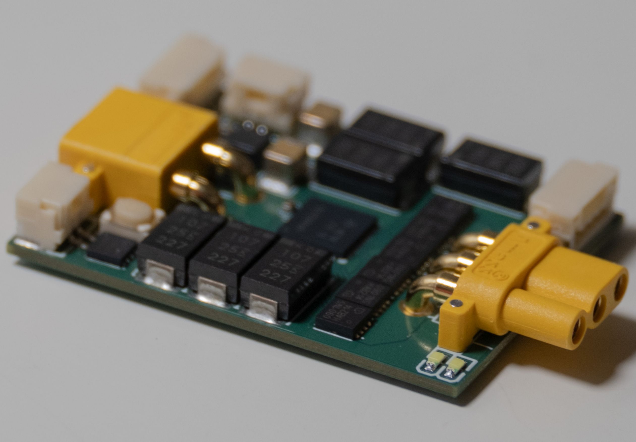
Powerful BRUSHLESS Motor Driver version 5 is a small brushless motor driver intended to drive motors up to 250W, a great fit for many robotics projects. Everything uses connectors for quick and easy wiring, and no soldering is required. The design is optimised for low power dissipation, with less than 5W power dissipation under all operating conditions. The current sensing circuitry uses RDS(on) based current sensing with temperature compensation for high efficiency. I2C and CAN bus is available for communication with the main microcontroller. Up to 200mA at 3.3V can be sourced from the I2C port, which can be used to power external circuitry.
Input voltage: 8-25V (30V surge), Continuous Output Current: 15A (Peak), 10.6A (RMS)
Small size: L: 47mm, W: 30mm, T: 7mm.
Connectors: Power: XT30, Motor: MR30, CAN: GH-2P, I2C: GH-4P, DEBUG: GH-2P.
Maximum PWM frequency: 50KHz
Maximum Motor Speed: 160000 ERPM
Supported Encoders: Sin/Cos Encoder (Recommended), Incremental Encoder optical or magnetic
Supported Motors:
- Robomaster M2006 P36
- Robomaster M3508 P19
- More motor and encoder combinations coming soon
PCB specs: 6 layer, 2oz copper on all layers, 1.2mm thickness, epoxy filled vias, min via hole 0.2mm, components on both sides.
Main parts:
STM32G431 microcontroller, 170MHz M4 CPU, optimised for motor control, with internal temperature sensor.
DRV8323S gate driver, 3x half bridge, with current sense amplifiers configured in RDS(on) mode.
BSZ0901NS MOSFET, ultra low RDS(on) of 1.7 milliohms at 25degc and 2.7 milliohms at 150 degc.
600uF onboard low ESR tantalum polymer capacitors, much smaller than similar electrolytic capacitors.
TJA1462A CAN transciever with signal improvement capability, operating at high speed of 8 mbps.
TPS54302 buck converter VCC -> 5V, TPS62A02 buck converter 5V -> 3.3V, AP7343D LDO 5V -> analog 3.3V.
Ordering Notes:
The DRV8323S chip on this board has offset calibration issues, which will result in a significant offset in the measured currents (500mA). Please check https://e2e.ti.com/support/motor-drivers-group/motor-drivers/f/motor-drivers-forum/1378175/drv8323-offset-calibration-issues for details. It is possible to perform additional calibration by measuring the residual offset and work around this issue.
You must choose 1.2mm PCB thickness and 2oz copper on all layers when ordering. If these options are not chosen then the board may overheat, and the temperature sensor compensation function will not work. The PCB is designed to be a heat spreader.
The XT30 connector stocked by JLCPCB is the 3mm lead height version. If you choose to use it, then the PCB will be thicker than expected. If you want the advertised PCB size, you can either use the 2mm lead height XT30 connector, or use sandpaper to remove the excess lead length.
When using JLCPCB Assembly the MOSFET used to enable the 3.3V output on the I2C and sensor connectors seems to have a high defect rate.
The MR30 motor connector and XT30 power connector are connected to the PCB without thermal reliefs for maximum heat dissipation. This means that these components need special care when soldering, and there is a chance JLCPCB wave soldering could produce poor results. When ordering please leave a remark that the connectors in wave soldering need higher temperature than normal otherwise they may not be soldered properly. It is also recommended that you have access to high quality PCB rework equipment in case of any problems with JLCPCB wave soldering process.
|
PCB from JLCPCB The solder on the connectors has not filled the hole, so it is making a bad electrical connection to the inner layers and top layer. |
Fixed PCB The solder on the connectors fills the hole completely and a solder fillet can be seen from the top. |
 |
 |
Panelisation:
|
When ordering the PCB it is recommended to order panels instead of single pieces, as the accuracy of the PCB edges is higher when you order panels. Please refer to the diagram on the right for an example panel configuration, where the top 3 PCBs have been rotated by 180 degrees (otherwise during assembly the components will overlap). Please note that V cut is not allowed on the long edge of the PCB, it is only allowed on the short edge. |
 |
Usage Notes:
To avoid short circuits, it is recommended to place a heat shrink over the PCB. The recommended heatshrink diameter is 30mm (+- 3mm).
The MOSFETs on the motor driver are designed to switch extremely quickly. The recommend IDRIVE settings are 260/520mA. Using these settings, the VDS switching time is around 30ns and the VGS switching time is around 200ns. However, if the fast switching generates too much electromagnetic interference, you can reduce the IDRIVE settings to make the MOSFETs switch slower, but doing this will increase power losses and cause the motor driver to heat up more.
The onboard capacitors can generate significant inrush current. Consider using an inrush current limiting solution, such as XT90S connector.
The 3.3V 200mA outputs do not have overcurrent protection, and the board could be damaged by short circuits on the output. Please be careful.
The motor driver is compatible with SimpleFOC library software.
Regenerative braking:
The motor driver by default has regenerative braking enabled. This means current will flow from the motor driver into the power supply when the motor is slowing down. This reverse current can damage the power supply if you are not careful. To avoid this, you need to add a TVS diode with breakdown voltage slightly (5-10%) higher than your power supply output voltage. This does not apply when using a battery to power the motor driver.
CAN Bus:
The motor driver uses a CAN SIC transciever, which means you can get away with not using a termination resistor for short cable runs under 50cm when all nodes use CAN SIC transcievers. This mode of operation also saves power, and does not require careful consideration of the cables.
For longer cable runs, a termination resistor is required to prevent signal reflections in the cable from causing problems. The value of the termination resistor needs to be as close as possible to the characteristic impedance of the cable. Do not just put a 120 ohm resistor as the termination resistor without knowing the characteristic impedance of the cable, it will not work.
The choice of cable is also very important, as it needs to have a constant characteristic impedance, and preferably be a differential pair. Some sources of cable you can use:
- CAN Bus cable, which provides the best signal integrity, is a twisted pair, has a characteristic impendance of 120 ohm, but is very expensive
- A twisted pair from an Ethernet cable, which provides good signal integrity, has a characteristic impedance of 100 ohm, and is cheap and readily available.
- Any 2 core cable, such as a section cut from a ribbon cable, which does not have great signal integrity due to not being a twisted pair, has a varying characteristic impedance you need to measure yourself, and is probably the cheapest type of cable available which will work.
- Do NOT use 2 separate cables to carry the CANH and CANL signals, it will not have a constant characteristic impedance and will not work.
The performance the CAN Bus has been tested using a 30m long jumper wire ribbon cable. The characteristic impedance of the cable was measured to be 200 ohms using trial and error method with an oscilloscope. A 200 ohm termination resistor was installed at both ends. The signal integrity was measured with the oscilloscope and was excellent, and there were no issues communicating at 8mbit/s.
Demo Video:
Featuring Robomaster M2006 P36 motor, motor driver in position control mode, position command sent every 500ms. Real time motor position is displayed on the screen.
Design Drawing
BOM
 Clone
CloneProject Members
Intellectual Property Statement & Reproduction Instructions
This is an open-source hardware project. All intellectual property rights belong to the creator. The project is shared on the platform for learning, communication, and research only; any commercial use is prohibited. If your intellectual property rights are infringed on EasyEDA, please notify us by submitting relevant materials in accordance with the Rules for Complaints and Appeals of IPR Infringement.
Users must independently verify the circuit design and suitability when replicating this project. All risks and consequences are borne by the user, and the platform assumes no liability.
 Empty
Empty
Comment