

 Completed
Open-Source Kicker Circuit
PROOpen-Source Kicker Circuit
License
:CC BY-NC-SA 4.0
Description
Open-Source Robotics Kicker Circuit Project
Overview

The open-source robotics kicker circuit is a groundbreaking initiative designed to deliver high-performance kicking capabilities for robots, particularly in soccer-playing applications. Robotics competitions like RoboCup demand precise and powerful mechanisms to interact dynamically with the environment, and this project addresses that need by providing an accessible and robust solution. By focusing on modularity, affordability, and safety, this circuit is ideal for robotics teams, hobbyists, and educators. Through an open-source approach, we aim to foster collaboration and innovation in the field of robotics.

Features and Key Design Elements
-
High-Voltage Energy Storage
-
Uses a bank of low-ESR electrolytic capacitors (at least 100 µF each) rated for 63 V to store up to 40 J of energy, providing the instantaneous burst required for strong kicks.
-
Capacitor charging is managed to maintain voltage within ±0.5 V, ensuring consistent performance shot‑to‑shot and reducing mechanical stress on the solenoid.
-
-
Modular Interface
-
Logic-level inputs (3.3 V/5 V tolerant) accept PWM or digital triggers, making the circuit plug‑and‑play with platforms such as Arduino, Raspberry Pi, or custom FPGA boards.
-
Standard Molex and JST connectors allow daisy‑chaining multiple kicker modules or integrating additional sensors (e.g., current shunts, temperature sensors).
-
-
Cost‑Effective Component Selection
-
All major parts—XL6019E1 boost converter, TC4427A gate driver, IRFP260N MOSFET—are available through multiple distributors at under USD 1 per unit when bought in 100‑piece lots, keeping the total BOM cost below USD 60.
-
PCB design emphasizes two‑layer boards with standard 1.6 mm thickness and 1 oz copper, minimizing fabrication costs at budget manufacturers like JLCPCB
-
Detailed System Design
The kicker architecture is logically partitioned into three subsystems—energy storage & boost conversion, switching & control logic, and safety & monitoring—each optimized for reliability and ease of integration.
-
Energy Storage & Boost Conversion
-
Input Stage: A 12 V DC supply (from robot battery or regulated adapter) feeds a synchronous boost converter based on the XL6019E1, capable of delivering up to 5 A at 48 V. Input filtering (220 µF, 75 V electrolytic + 0.1 µF ceramic) mitigates switching noise and protects upstream regulators.
-
Capacitor Bank: Four 100 µF, 63 V low‑ESR capacitors in parallel store energy. Their combined capacitance of 400 µF yields an energy capacity of ~46 J at 48 V. Layout emphasizes short, wide traces (<5 mm length) and heavy copper pour to handle high ripple currents.
-
Charge Control: The microcontroller regulates the boost converter’s enable pin via PWM, closing a feedback loop that holds the capacitor bank at a user‑defined target voltage. Charging halts automatically upon reaching that voltage or upon detecting an overcurrent fault.
-
-
Switching & Control Logic
-
Driver Stage: A TC4427A dual MOSFET gate driver boosts logic inputs to drive the IRFP260N, ensuring sub‑50 ns rise/fall times for crisp, repeatable actuation. A bootstrap circuit supplies the high‑side drive voltage when using an H‑bridge configuration for bidirectional kicking.
-
Discharge Path: When triggered, the MOSFET closes the circuit between the capacitor bank and the solenoid coil, releasing stored energy in a controlled pulse. The duration and timing of the pulse are precisely managed by the microcontroller’s hardware timers, allowing programmable kick profiles.
-
Logic Compatibility: Input thresholds are clamped with Schottky diodes and 10 kΩ pull‑downs, making the board tolerant of noisy signals and protecting against accidental overvoltage from 5 V systems.
-
-
Safety & Monitoring
-
Bleeder Network: After discharge, 10 kΩ resistors bleed residual charge safely. These resistors are sized to limit bleed current to <0.5 mA for minimal energy waste while ensuring a full discharge in under 60 seconds.
-

-
Switching and Control Logic:
A TC4427A gate driver is used to handle the high-speed switching required for precise operation. This driver ensures the MOSFET (IRFP260N) can switch rapidly and efficiently, directing the capacitor’s stored energy to the solenoid kicker.
External logic inputs are compatible with both 3.3V and 5V systems, making the circuit versatile for a wide range of microcontroller platforms.

-
Safety Features:
Discharge resistors are integrated into the design to safely dissipate stored energy when the system is idle, preventing accidental activation.
Overcurrent protection and fault detection circuits monitor the system’s health, ensuring reliable operation and protecting components from damage.


Applications and Use Cases
The open-source kicker circuit has broad applications, including:
Competitive Robotics: Designed for soccer-playing robots, this circuit enhances performance by delivering precise and powerful kicks. It is particularly useful for events like RoboCup, where high-speed decision-making and robust mechanisms are crucial.
Educational Platforms: The project provides an excellent opportunity for students and educators to explore high-voltage circuits, energy storage systems, and robotics integration. It can serve as a practical teaching tool for advanced electronics and embedded systems.
Prototyping and Research: Researchers and hobbyists can use the circuit as a foundation for developing advanced robotic mechanisms. Its modularity and adaptability make it a versatile starting point for experimentation.
Open-Source Commitment and Resources
A key aspect of this project is its commitment to open-source principles. All design files, including schematics, PCB layouts, and firmware, will be made publicly available under an open-source license. This ensures that users can replicate, modify, and improve the design to suit their specific needs.

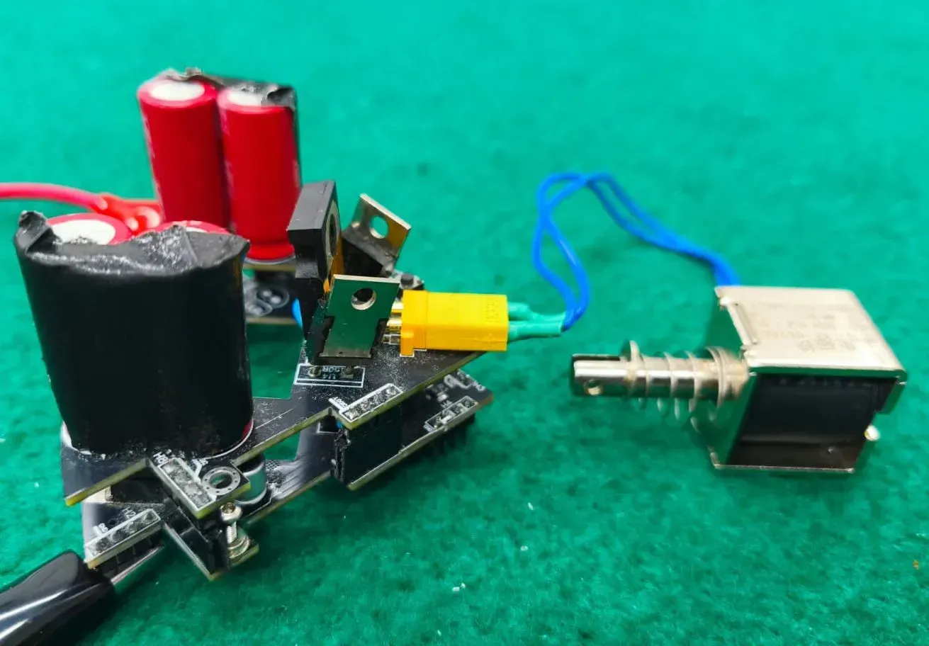
Visualization and Component Placement
The project’s documentation includes placeholders for schematic and PCB images, making it easier for users to visualize the design. These diagrams will illustrate component placement, wiring paths, and integration points, providing a clear reference for assembly and troubleshooting. Including visual aids ensures that even novice users can confidently work with the circuit.
Conclusion
The open-source robotics kicker circuit represents a significant step forward in making high-performance robotics components accessible to a wide audience. Its combination of affordability, safety, and modularity ensures that it meets the needs of diverse users, from beginners to advanced robotics teams. By adopting an open-source philosophy, this project encourages innovation and collaboration, paving the way for new advancements in robotics technology. With detailed documentation and support resources, the kicker circuit is poised to become a valuable tool in the robotics community.
Design Drawing
BOM
 Clone
CloneProject Members
 Empty
Empty
Comment