Your EasyEDA usage duration is brief. In order to avoid advertising information, this action is not supported at present. Please extend your EasyEDA usage duration and try again.
Editor Version×
Standard
1.Easy to use and quick to get started
2.The process supports design scales of 300 devices or 1000 pads
3.Supports simple circuit simulation
4.For students, teachers, creators
Profession
1.Brand new interactions and interfaces
2.Smooth support for design sizes of over 5,000 devices or 10,000 pads
3.More rigorous design constraints, more standardized processes
## DxMini24
Dev board for AVR*DB32 with optional NRF24L01+ SMD module
Compatible with
* AVR128DB32
* AVR64DB32
* AVR32DB32
(and probably AVR128DD32 in the future)
It may also work with AVR*DA32 MCUs, but it's not tested.
The board was designed for hand soldering.
This is a smaller version (with less pins) of this board: [https://oshwlab\.com/Miraculix200/minimegazero24\_copy\_copy\_copy\_copy](https://oshwlab.com/Miraculix200/minimegazero24_copy_copy_copy_copy)
## Features
This is a new generation of AVR MCUs which has builtin OPAMPs, 24MHz CPU speed at 1.8V, 12-bit ADC, increased noise immunity, builtin level shifter (MVIO) and more.
The MVIO section is within the rectangle on the silk screen.
To use it as a level shifter, remove the 0 Ohm resistor and connect VDDIO2 to a voltage source, e.g. 5V. Then the signals in the MVIO section have 5V. On this board you can enable the I2C function for 2 of the pins within the MVIO section, so you don't need to use a level shifter for 5V I2C modules.
Instead of using a 0 Ohm resistor for normal (3.3V) operation, you could also connect the VDDIO2 pin to the 3V3 pin of the board.
It is recommended that you add an external 1uF capacitor to the VDDIO2 pin, when powering it seperately.
If you leave the 0 Ohm resistor in place, the MVIO section will be fed with 3.3V.
**WARNING**: Do not connect a seperate voltage source to VDDIO2 before you have removed the 0 Ohm resistor.
Optionally you can solder a NRF24L01+ SMD module to the board. Use GPIO 13 as CE pin and GPIO 7 as CS pin. GPIO 25 is connected to the IRQ pin of the NRF24L01+ module.
Example code to measure battery voltage without a voltage divider (using MVIO):
[https://gist.github.com/Miraculix200/0cae0e6b91275d1f9045b3df7d822335](https://gist.github.com/Miraculix200/0cae0e6b91275d1f9045b3df7d822335)
## Bootloader
To burn the bootloader, start by connecting your USB to serial board to your dev board like this
![Screen Shot 01-19-21 at 12.49 PM.png](//image.easyeda.com/pullimage/juULYw8OMXpB5uR5bu0Oq6GTemGMzo9vG3r33FtI.png)
**WARNING**: Do not power the board with 5V through the 3V3 pin if a NRF24L01+ module is present in the circuit. Otherwise you will damage your NRF24L01+
### Using Arduino IDE with DxCore
Install DxCore using the Board Manager of Arduino IDE, following the instructions here:
[https://github.com/SpenceKonde/DxCore/blob/master/Installation.md](https://github.com/SpenceKonde/DxCore/blob/master/Installation.md)
DxCore now includes pymcuprog, so you can easily burn the bootloader by selecting "**Serial Port + 4.7k Resistor (pyupdi style)**" as programmer, then selecting "**Burn Bootloader**".
Now you can directly connect your FTDI board to the FTDI header on the dev board, and flash it through Arduino IDE, like you would flash a Arduino Pro Mini.
### Using pymcuprog by Microchip
If you prefer to play around with the various possibilties pymcuprog gives you, you can start by burning the bootloader like this
1. Download the DxCore bootloader: [https://raw\.githubusercontent\.com/SpenceKonde/DxCore/master/megaavr/bootloaders/hex/optiboot\_dx128\_ser0\.hex](https://raw.githubusercontent.com/SpenceKonde/DxCore/master/megaavr/bootloaders/hex/optiboot_dx128_ser0.hex)
2. Install Python if you don't have it already
3. Install pymcuprog using Pythons `pip install pymcuprog`
4. Connect your serial (e.g. FTDI Basic 3.3V) to UPDI and burn the bootloader like this
`pymcuprog -t uart -u COM3 -c 9600 -d avr128db32 write -f optiboot_dx128_ser0.hex`
5\. Set the BOOTSIZE fuse
`pymcuprog -t uart -u COM3 -c 9600 -d avr128db32 write -m fuses -o 8 -l 0x01`
6\. Set the SYSCFG/RSTPINCFG fuse
`pymcuprog -t uart -u COM3 -c 9600 -d avr128db32 write -m fuses -o 5 -l 0xc8`
Note that if you want to overwrite your bootloader with a new bootloader, you need to manually erase the chip like this: pymcuprog -t uart -u COM3 -c 9600 -d avr128db32 erase
## Uploading sketches
Install DxCore in your board manager, following the instructions here:
[https://github.com/SpenceKonde/DxCore/blob/master/Installation.md](https://github.com/SpenceKonde/DxCore/blob/master/Installation.md)
## Sources
[https://github.com/SpenceKonde/DxCore/blob/master/megaavr/variants/32pin-standard/pins_arduino.h](https://github.com/SpenceKonde/DxCore/blob/master/megaavr/variants/32pin-standard/pins_arduino.h)
[https://www.microchip.com/wwwproducts/en/AVR128DB32](https://www.microchip.com/wwwproducts/en/AVR128DB32)
[https://ww1\.microchip\.com/downloads/en/DeviceDoc/AVR128DB48\_Curiosity\_Nano\_Schematics\.pdf](https://ww1.microchip.com/downloads/en/DeviceDoc/AVR128DB48_Curiosity_Nano_Schematics.pdf)
## Photos
![R0039482.jpg](//image.easyeda.com/pullimage/TX2tNDqoCwzVObAUL6j8MDRfJ0oO6MFEjyqKdEZJ.jpeg)![R0039488.jpg](//image.easyeda.com/pullimage/DcE1ZV7Fbt5ZSicIY6px2dvkawpaVGySy5fElYpf.jpeg)![R0039473.jpg](//image.easyeda.com/pullimage/ojRBOfAokf25RePP3XFqesn0LAxGF1g99Rwvzc1i.jpeg)
Forked project will be set private in personal workspace. Do you continue?
Clone
Project
The Pro editor is about to be opened to save as. Do you want to continue?
private message
Send message to miraculix200
Delete
Comment
Are you sure to delete the comment?
Report
DxMini24 (AVR128DB32)
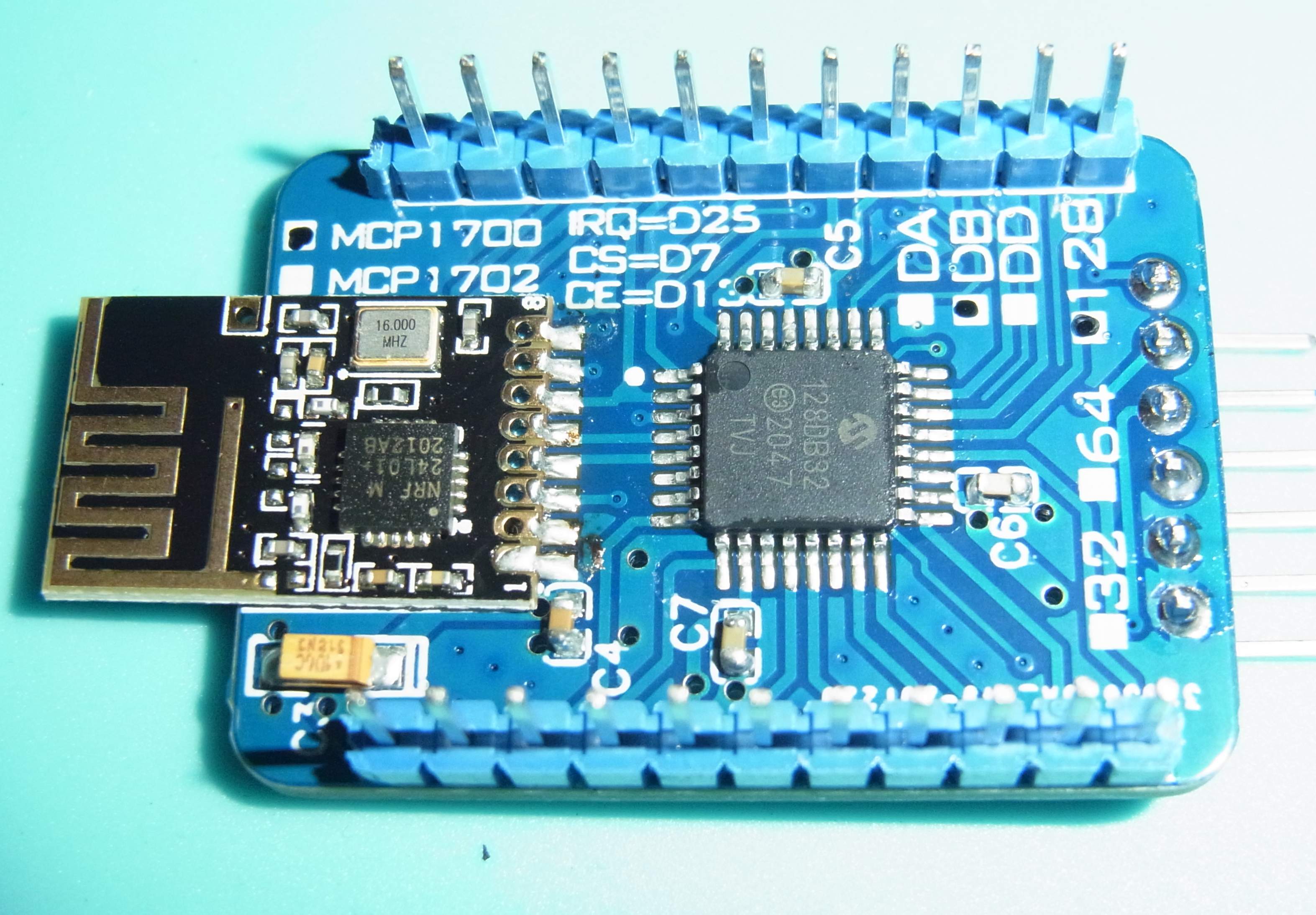
AVR128DB32 dev board with NRF24L01+
Announcer: Miraculix200
Creation time: 2020-12-22 14:55:56
Published time:
2021-02-09 22:35:41
*
Report type:
Please select report type
*
Report reason:
Please fill in the reason for your report and the content is 2-1000
words
*
Upload image:
+
Upload image
*
Email address:
Please fill in your email address
Report
*
Report type:
Please select report type
*
Report reason:
Please fill in the reason for your report and the content is 2-1000
words
*
Upload image:
+
Upload image
*
Email address:
Please fill in your email address
Report
Submitted successfully! The review result can be viewed in the personal
center, review notification.
Kind tips
Your EasyEDA usage duration is brief. In order to avoid advertising information, this action is
not supported at present. Please extend your EasyEDA usage duration and try again.
Share
Project
Copy
Copy
Scan the QR code and open it on the mobile terminal