

 Ongoing
Car DC-DC step down Converter
STDCar DC-DC step down Converter
License
:CC-BY 3.0
Description
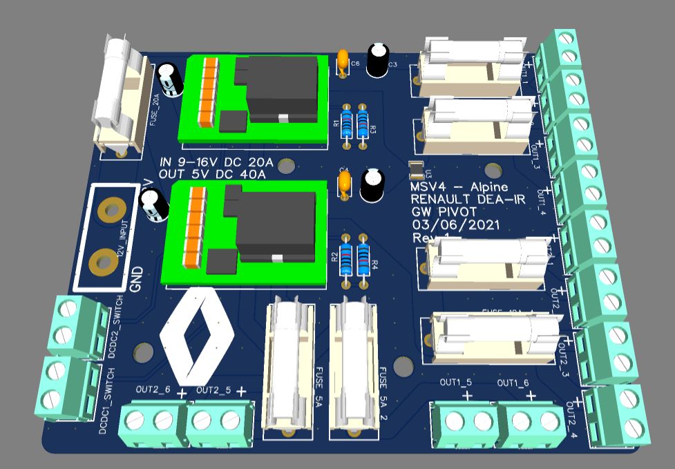
The project only uses through-holes standard components.
You can just have the PCB Done, and then assemble the modules, Fuse holders, capacitors, and screw terminals.
WARNING : the PCB needs to have 2 OZ /ft² of copper planes to ensure right thermals and dimensionning of the traces.
INPUT : 9-16 V DC - 20 A
OUTPUT : 5V DC - 40 A
All outputs are fuse-protected
Input is also fuse protected (however if you connect this to the battery of your car, you need to have a fuse close to the battery to protect the wire going to the PCB)
The Input wires can be directly soldered on the board (using at least 6mm² wires), and a connector like XT60 can be used if disconnection is necessary.
There is a ZERO ohm resistor that can be either populated or not populated.
If not populated, the two Modules each supply half of the outputs. Otherwise, output power is commonalized.
OUT1_x are outputs using module 1
OUT2_y are outputs using module 2
Each modules has 6 outputs: 4 outputs rated at each 5 Amps (1.5² mm wire recommanded) and 2 outputs rated each at 2.5 A.
Each module can be independantly activated or disactivated using the DCDCn_Switch header (for instance by using a bistable switch)
The TDK Lambda module used is a good quality one, can be found for around 30€ on Mouser or Digikey.
Thermal behavior has not been tested, but at full output power, self heating should be around 10W, so forced air might be required to avoid modules self-protection.
Use this module at your own risk, there is no warranty that this design is safe for your application.
Don't hesitate to message me if you want more details on this design.
Design Drawing
BOM
 Clone
CloneProject Members
 Empty
Empty
Comment