

 Completed
Building a Custom Mechanical Keyboard: A Complete Hardware and Firmware Journey
PROBuilding a Custom Mechanical Keyboard: A Complete Hardware and Firmware Journey
License
:MIT License
Description
My Motivation
From the very beginning of my journey with computers, membrane keyboards were the only type of keyboard I had ever used. Over time, I noticed a common problem with traditional membrane keyboards: their performance gradually degrades with regular use. Dust, debris, and moisture can accumulate beneath the rubber dome layers, causing keys to feel stiff, inconsistent, or unresponsive after just a few months of use. The typing experience becomes uneven, requiring more force to actuate certain keys, which can be frustrating during long typing sessions.
My desk is positioned directly in front of a large window, which means a significant amount of dust regularly enters my workspace. As a result, dust and fine particles easily accumulate inside membrane keyboards over time. Within just a few months, I had to replace two keyboards due to stiff keys and inconsistent performance. This repeated experience was both frustrating and disruptive, and it highlighted the limitations of membrane keyboards in dusty environments. Ultimately, this pushed me to look for a more durable alternative, leading me to try a mechanical keyboard.
From the very first days of using it, I became fascinated. I started noticing the feel of different switches, the sound of each keystroke, and how small design choices could dramatically change the typing experience. What began as simple curiosity quickly turned into a deep exploration of the mechanical keyboard community. I discovered a vast ecosystem of switches, keycaps, layouts, and custom designs, along with countless DIY projects shared by makers around the world.
As an electronics hobbyist and maker, this discovery was incredibly motivating. Seeing others design and build their own keyboards sparked a strong desire in me to do the same. I spent time researching existing DIY keyboards, learning from their designs, and understanding the technical decisions behind them. Eventually, that curiosity and research turned into action, and I set out to design and build my own mechanical keyboard from scratch—not just as a personal project, but as something I could share with the community that inspired me.
In this article, I document my complete journey of designing and building a custom mechanical keyboard—from schematic design and PCB layout to firmware development using QMK and final assembly. This project was both a learning experience and a practical exploration of hardware–software integration, aimed at creating a keyboard tailored to my typing preferences and technical goals.
Project Overview & Design Philosophy
Like many electrical and embedded systems engineers, I have always been drawn to PCB design. Beyond functionality, I genuinely enjoy the visual and artistic side of PCBs—the symmetry of traces, clean routing, balanced component placement, and how good design can be both electrically sound and visually pleasing. For me, a PCB is not just a circuit; it is also a form of engineering art.
This philosophy strongly influenced the design of my custom mechanical keyboard. From the beginning, I wanted the keyboard PCB to reflect both technical reliability and aesthetic intention. In addition to ensuring a robust key matrix, proper signal routing, and compatibility with QMK firmware, I paid close attention to trace alignment, component symmetry, and overall layout cleanliness. Wherever possible, I treated the PCB as a visible design element rather than something to be hidden.
The goal of this project was to design a fully custom mechanical keyboard from the ground up—starting with the schematic, moving through PCB layout and mechanical design, and finishing with firmware development and final assembly. By controlling every stage of the process, I was able to balance electrical performance, firmware flexibility, and visual aesthetics. This project represents not only a functional input device, but also my personal approach to embedded hardware design, where engineering precision and visual design go hand in hand.
Keyboard Specifications
The keyboard was designed as a tenkeyless (TKL) layout, striking a balance between functionality and desk space efficiency. It incorporates modern features commonly found in high-end custom keyboards while remaining accessible to the DIY community.
Key specifications are summarized below:
| Feature | Description |
|---|---|
| Layout | Tenkeyless (TKL) |
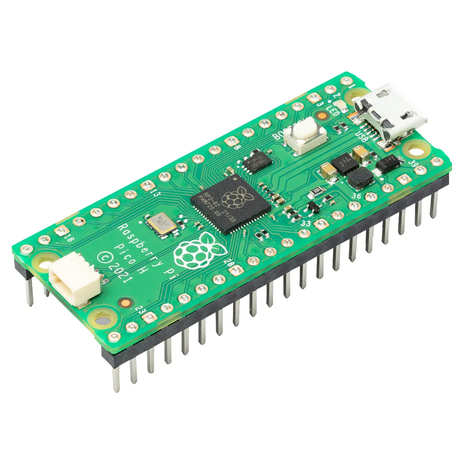
| MCU | Raspberry Pi Pico (RP2040) |
| Firmware | QMK |
| Connectivity | USB Type-C |
| Switch Type | Mechanical switches (hot-swappable) |
| RGB Lighting | Per-key RGB lighting |
| Encoder | Rotary encoder for volume/media control |
| Display | Small OLED display for status and feedback |
| Mount Style | Custom (tray / top / gasket – update if needed) |
| Power | USB-powered |
The choice of the Raspberry Pi Pico was intentional. Its popularity within the DIY and embedded systems community, combined with strong documentation and QMK support, made it an ideal controller for this project. Using a USB Type-C connector ensures reliable connectivity and aligns the design with modern hardware standards.
Visual Design, PCB Aesthetics, and Component Placement
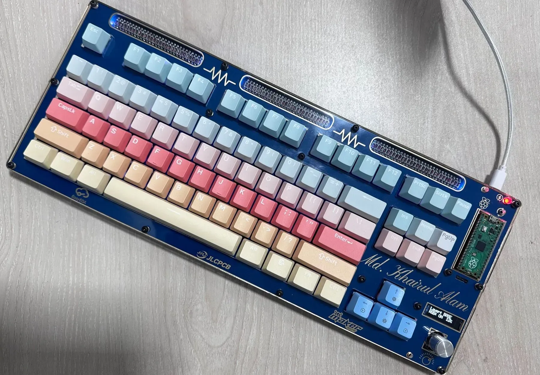
One of the defining aspects of this keyboard is that the PCB itself is treated as a visible design element rather than something hidden inside a closed case. As an electronics and embedded systems enthusiast, I have always appreciated PCB art—the balance between electrical correctness and visual harmony—and this philosophy strongly influenced the overall look of the keyboard.
The keyboard uses a transparent acrylic-style top case, intentionally exposing the PCB, silkscreen logos, and components. This makes routing quality, symmetry, and alignment immediately visible, so extra care was taken during layout to keep traces clean, evenly spaced, and visually structured.
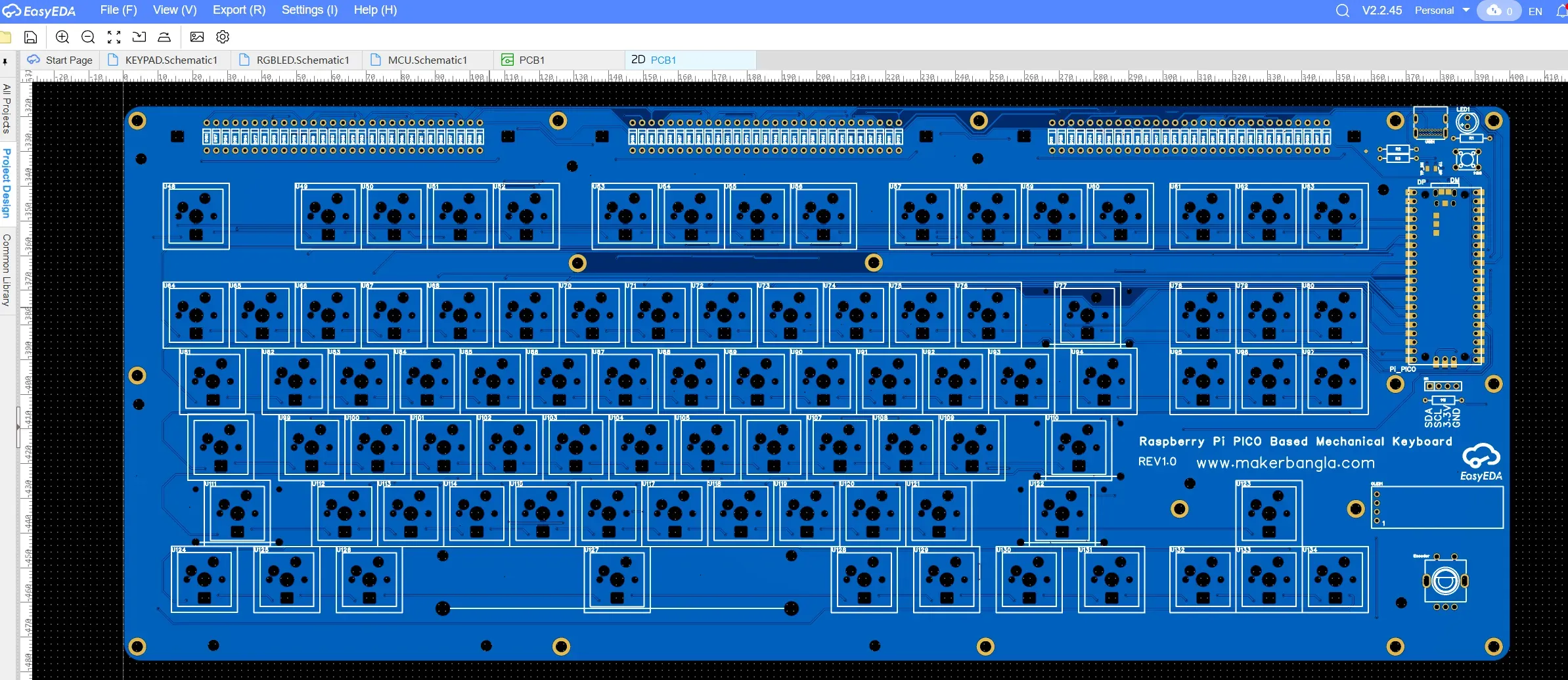
Component placement was also guided by both functionality and aesthetics. The Raspberry Pi Pico is mounted on the right side of the PCB, making it clearly visible and easily accessible. This not only highlights the heart of the system—the RP2040—but also reflects the DIY spirit of the project, using a widely recognized development board within the maker community.
The rotary encoder and OLED display are positioned in the bottom-right area, forming a dedicated control and information zone. This separation keeps the main typing area uncluttered while allowing quick access to secondary functions. The OLED displays real-time status information such as the active layer and RGB brightness, while the rotary encoder provides intuitive physical control for actions like volume adjustment and lighting control.
Per-key RGB lighting is integrated across the board, and the transparent enclosure allows the lighting to interact directly with the PCB surface.
Overall, the visual design of the keyboard reflects my approach to PCB design: clean, intentional, and expressive. Every visible element—traces, components, graphics, and lighting—serves both a technical purpose and an aesthetic role, reinforcing the idea that good hardware design can be both functional and visually engaging.
Schematic Design and Matrix Architecture
When I decided to design the schematic for this keyboard, I quickly realized that most open-source DIY mechanical keyboard projects are built using KiCad. While KiCad is widely adopted within the keyboard community, I did not have enough practical experience with it at the time. Instead of switching tools and slowing down the project, I chose to work with EasyEDA, a platform I was already comfortable with and had used in previous PCB designs.
One of the first challenges I encountered was related to switch footprints. While searching EasyEDA’s component libraries, I found that there was no complete footprint that matched my requirementsn, specifically a footprint that combined MX-style switch pads, support for hot-swappable sockets, and the correct circular cutout for the mechanical switch housing. Most available footprints were either incomplete or designed for solder-only switches.
To solve this, I decided to modify an existing footprint and customize it to fit my design needs. I carefully adjusted the pad placement to support hot-swappable sockets and added the required mechanical cutouts to ensure proper switch fitment. This step was critical, as the footprint directly affects both mechanical compatibility and electrical reliability. Once finalized, this custom footprint became the foundation for the entire key matrix.
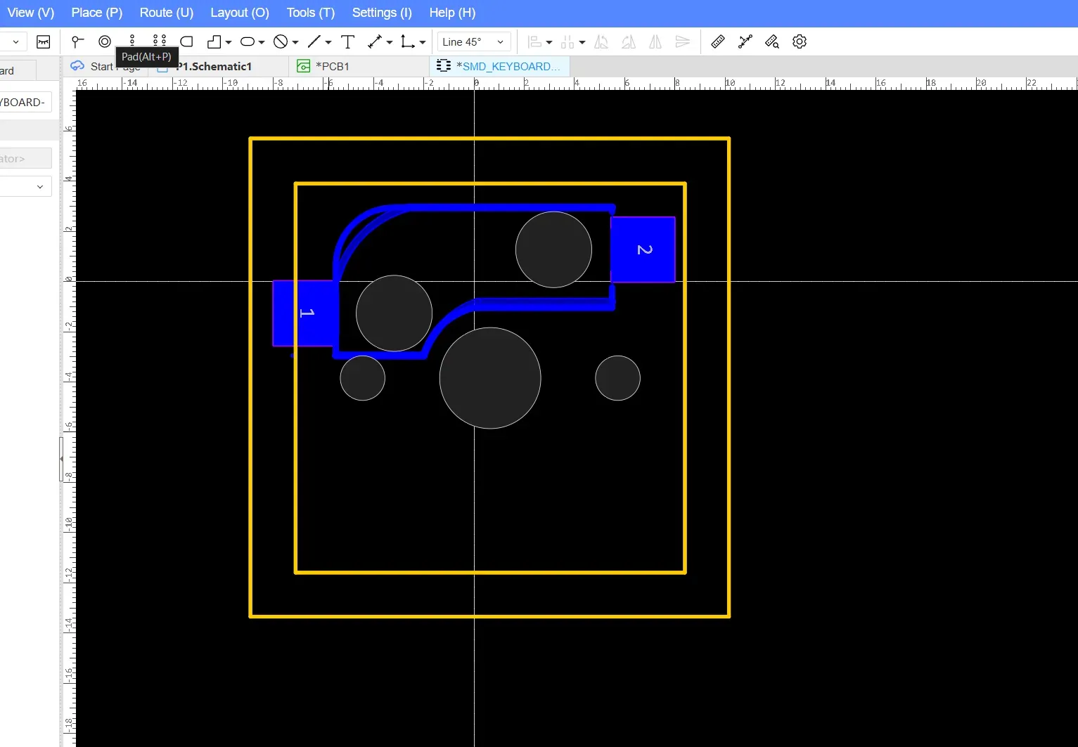
Below is the available footprint for the mechanical key switch.
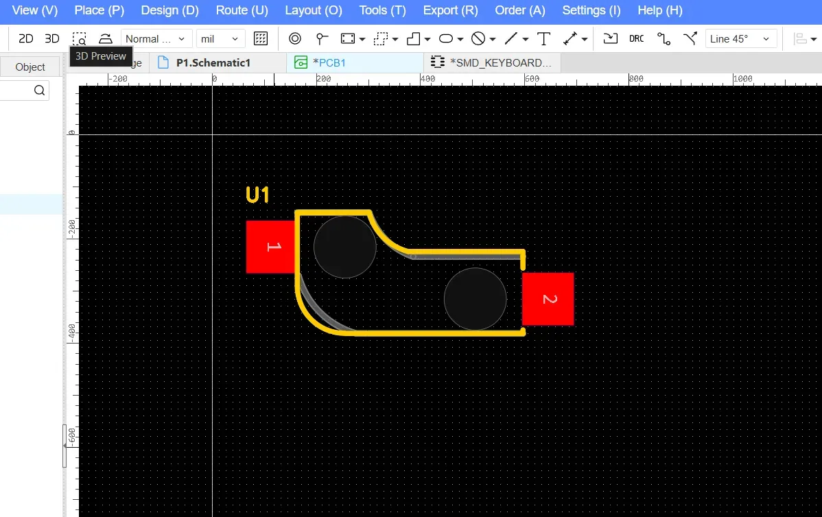
I modified the original footprint to match the design shown below. The footprint boundary was carefully defined to ensure that switches could be placed side by side at the correct spacing, making alignment straightforward and maintaining standard key-to-key distances across the layout.
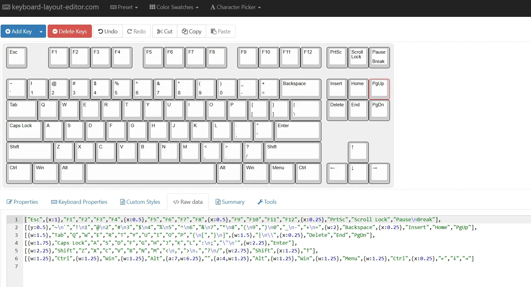
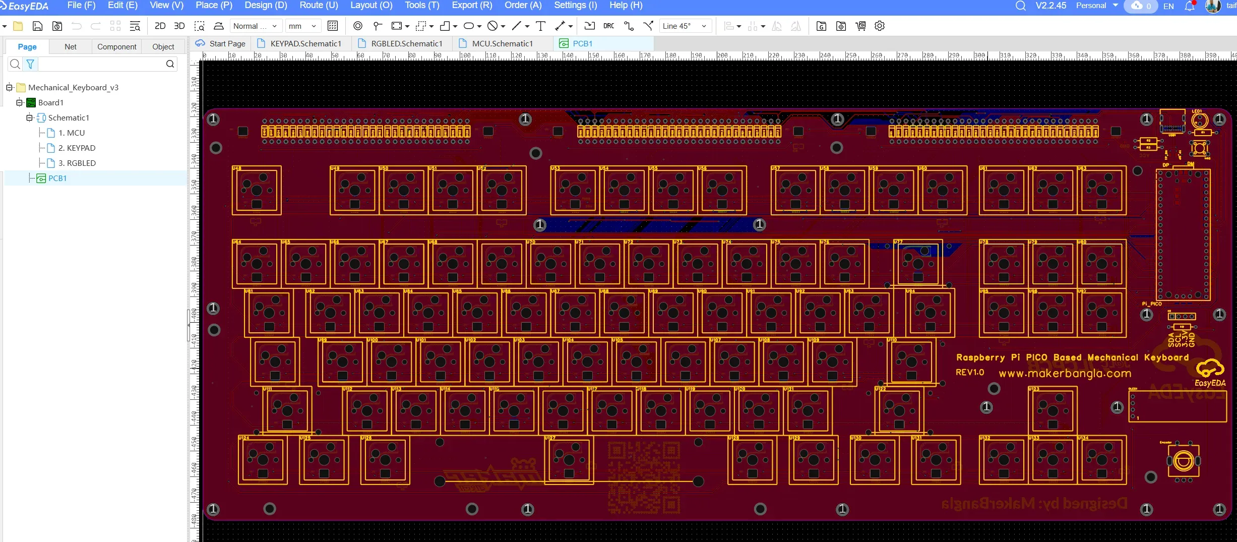
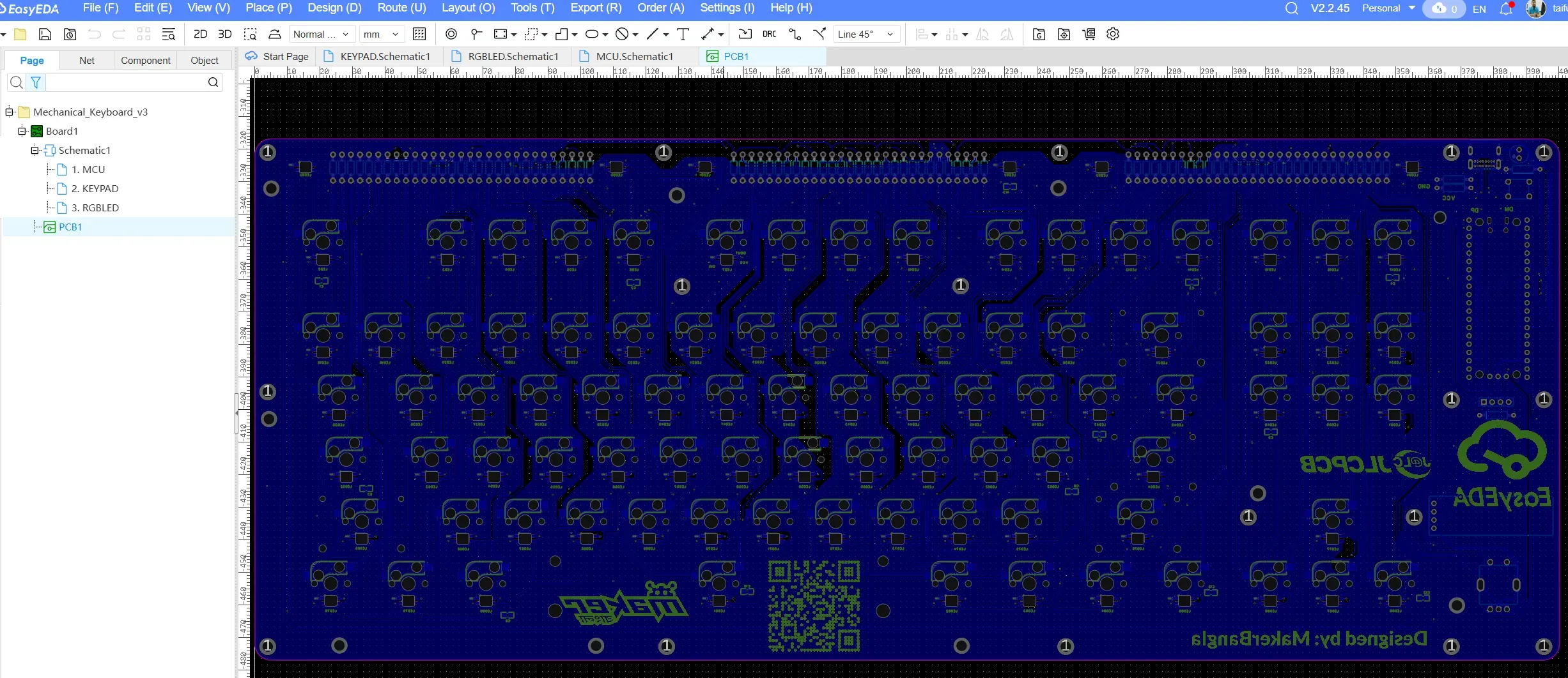
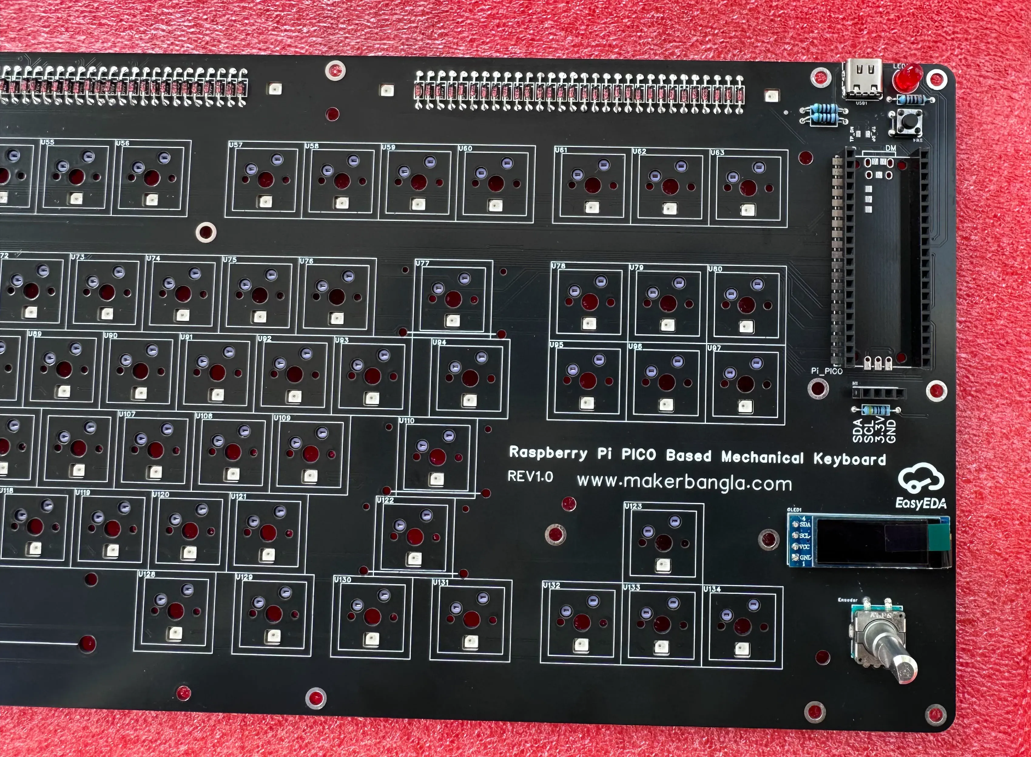
Since the keyboard consists of 87 keys, I added all 87 switches to the schematic and organized them into a matrix configuration. As shown in the screenshot, the keys are arranged across six rows and fourteen columns, reflecting the logical structure of the key matrix used for scanning and firmware mapping.
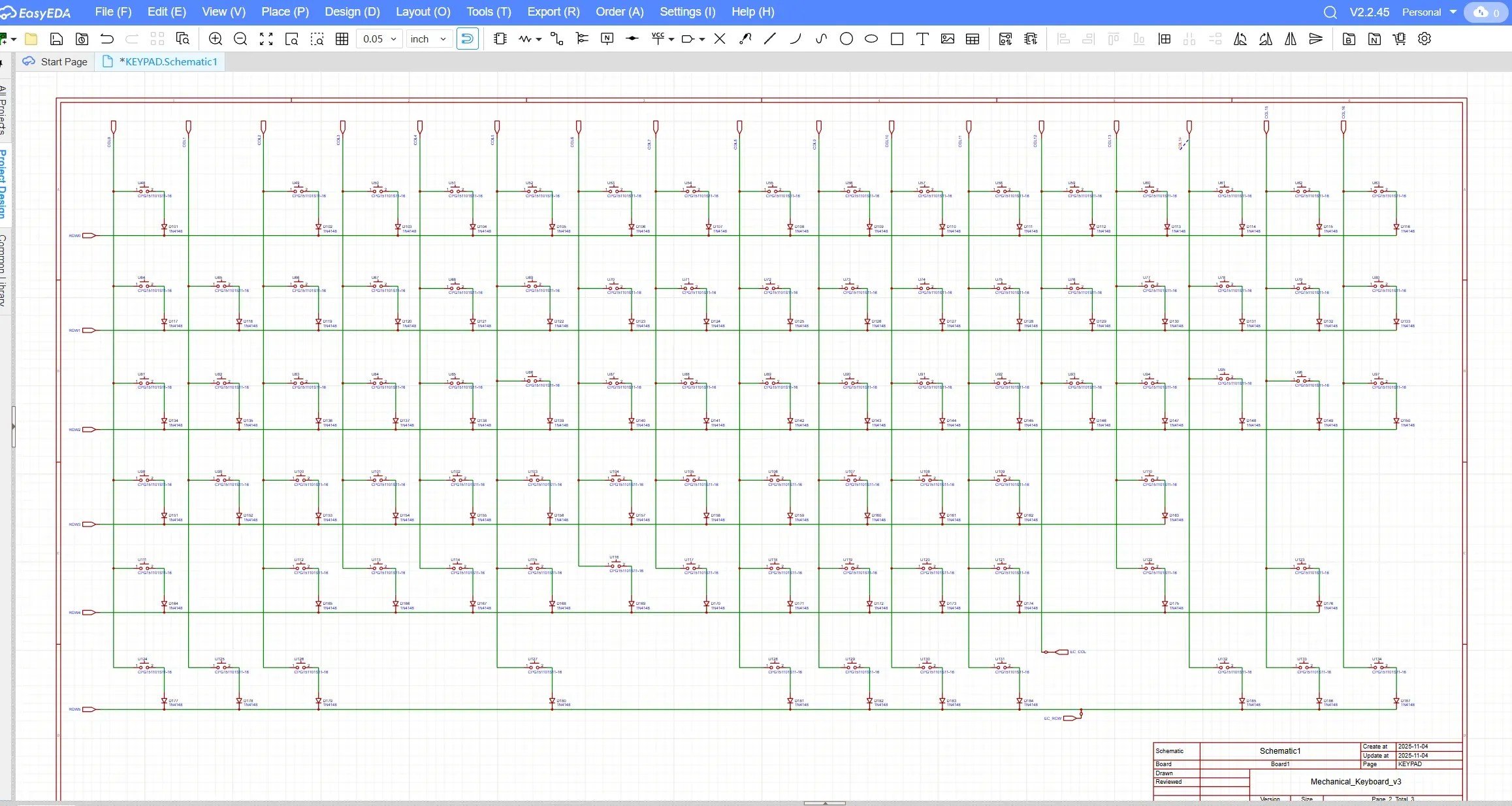
The row–column structure was chosen not only to reduce pin usage but also to keep the matrix logically organized and easy to route on the PCB. Grouping keys in this way helped maintain clean schematic organization and later simplified both PCB routing and QMK firmware configuration.
To prevent ghosting and ensure reliable key detection, I added a signal diode for every switch, oriented from the column to the row. This diode-per-key configuration allows proper current flow during matrix scanning and enables full n-key rollover.
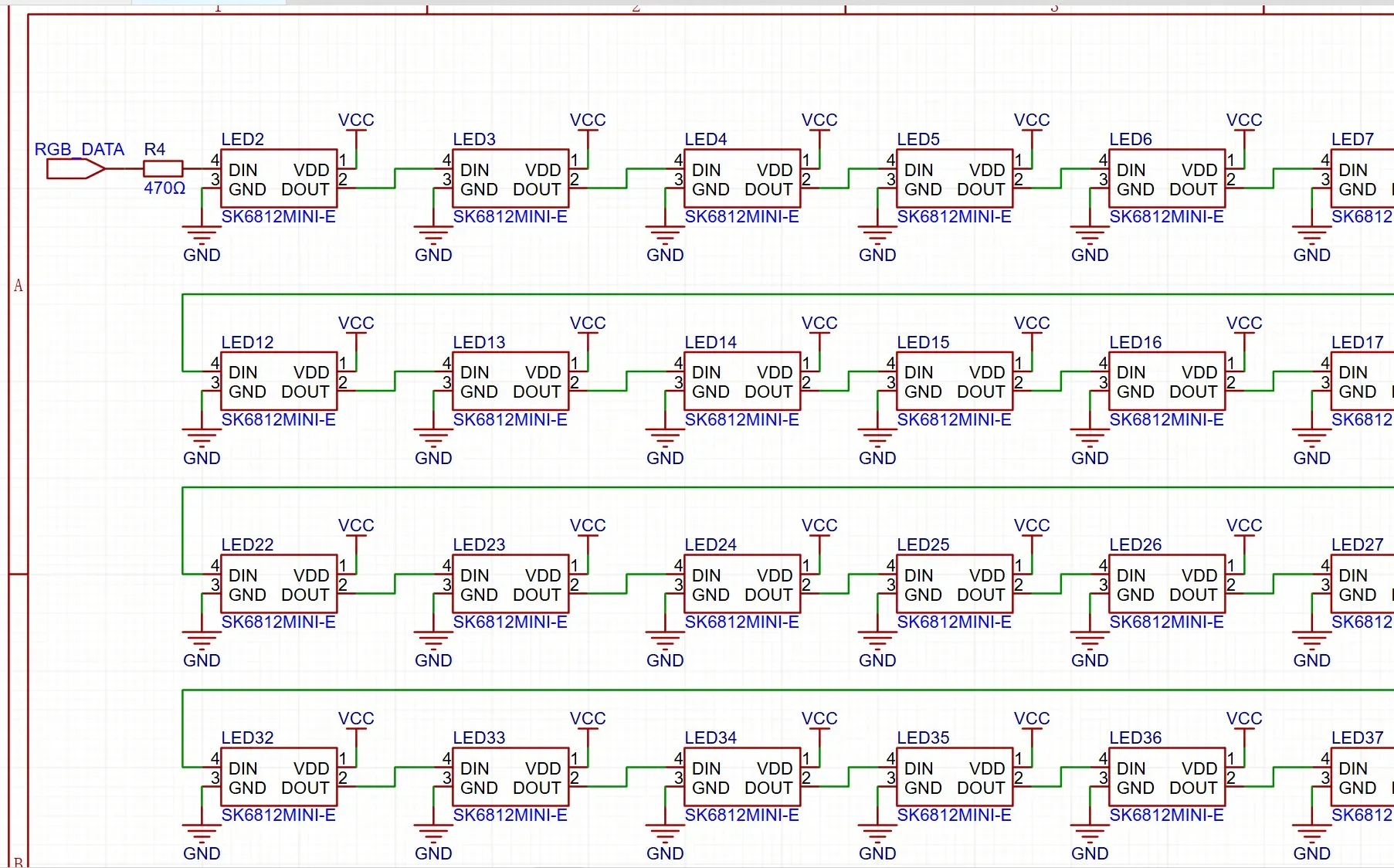
RGB Lighting Circuit
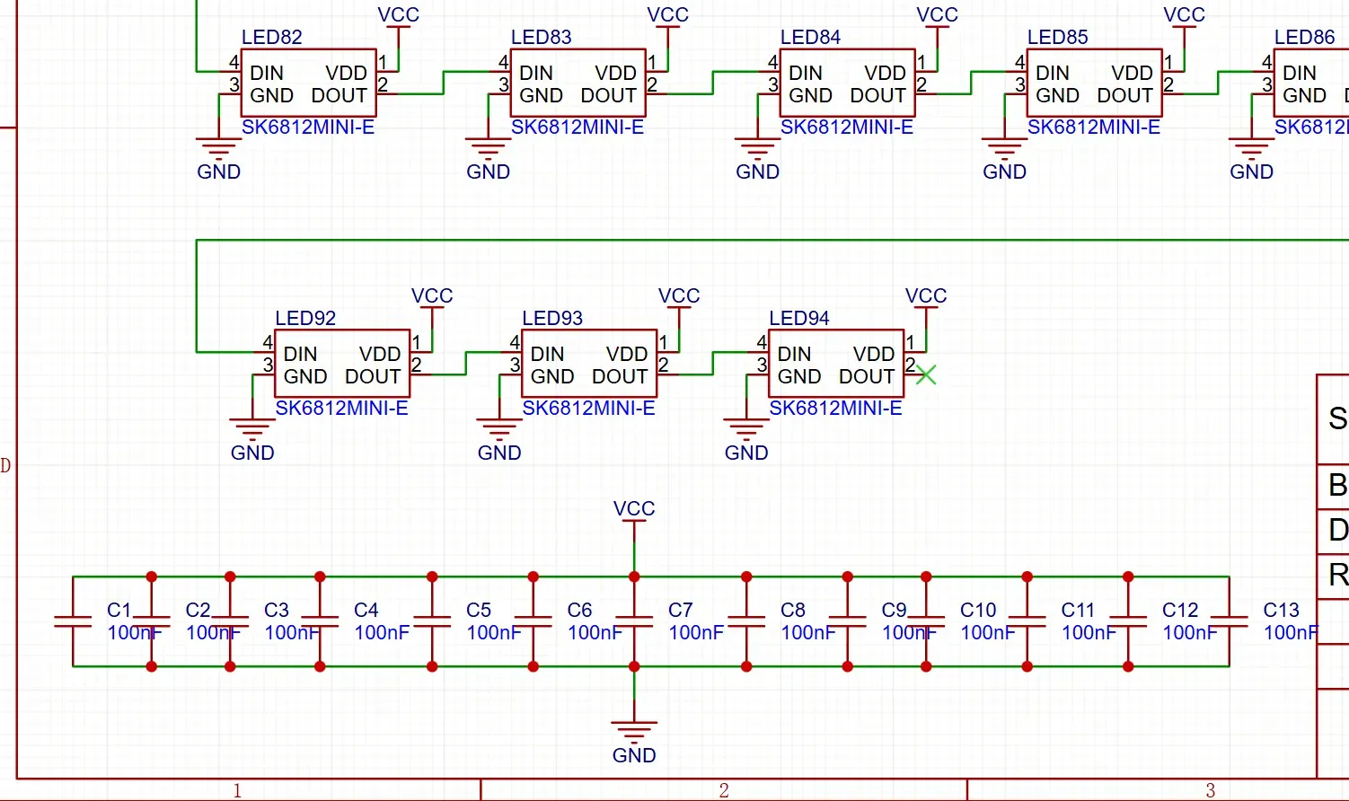
The keyboard includes 87 per-key RGB LEDs, corresponding to each switch location. In addition to these, six extra addressable RGB LEDs were added for decorative purposes, bringing the total number of LEDs to 93. These additional LEDs are positioned outside the main switch matrix and are intended purely for aesthetic enhancements, such as accent lighting that complements the exposed PCB design.
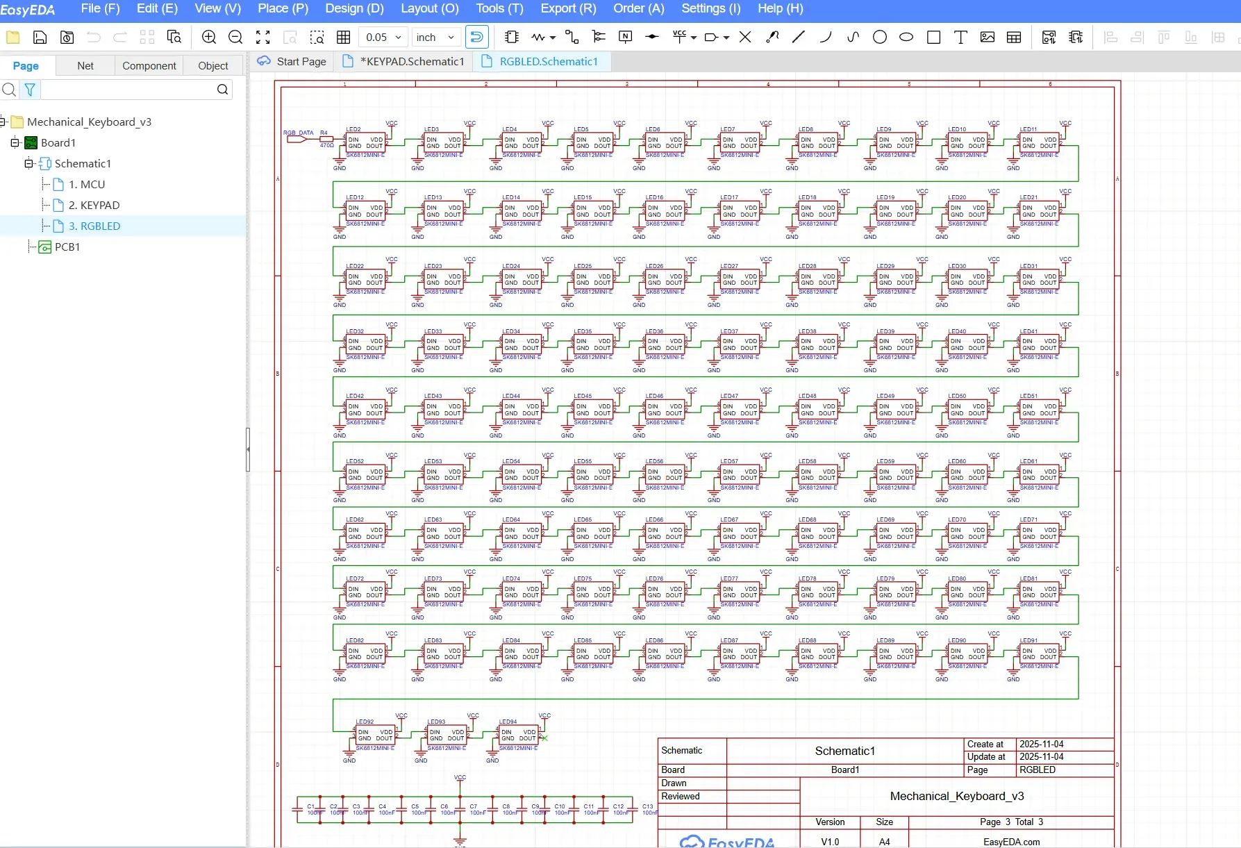
All RGB LEDs are controlled through a single daisy-chained data line, which simplifies both PCB routing and firmware implementation. To improve signal integrity and protect the first LED in the chain, a 470 Ω series resistor was added to the RGB data line. This resistor helps reduce signal ringing and current spikes, particularly at higher data rates, ensuring more reliable communication between the microcontroller and the LED chain.
Special attention was also given to power distribution and decoupling. Multiple decoupling capacitors were placed across the RGB power rail to stabilize the supply voltage when a large number of LEDs are active simultaneously. These capacitors help prevent voltage drops, flickering, and electrical noise that could otherwise affect LED performance or interfere with other parts of the system.
Together, these design choices contribute to a stable, reliable, and visually consistent RGB lighting system, even under high brightness and dynamic lighting effects.
OLED Display
A 128×32 OLED display was added to the design to provide real-time visual feedback such as active layers, RGB brightness, and system status. To minimize GPIO usage, the display is connected via the I²C interface, sharing the standard SDA and SCL lines.
Using I²C allowed the OLED to integrate cleanly into the system without consuming additional digital pins needed for the key matrix. Proper pull-up resistors were included in the schematic to ensure reliable communication and signal stability.
Rotary Encoder Integration
The rotary encoder was integrated as both a functional and interactive input device. The encoder’s push switch is connected and treated as a regular key within the key matrix, allowing it to be easily remapped using QMK like any other key.
The two quadrature output pins of the encoder are connected to two dedicated digital GPIO pins on the Raspberry Pi Pico. This configuration enables accurate detection of rotational direction and speed, while keeping the firmware logic straightforward and responsive.
USB Type-C Interface
Although the official Raspberry Pi Pico board uses a Micro-USB connector, this design incorporates a USB Type-C port for improved durability, reversibility, and compatibility with modern devices. The USB Type-C connector is wired according to standard USB 2.0 specifications and interfaces directly with the Pico’s USB data lines.
This approach preserves full USB functionality while modernizing the physical interface, making the keyboard more convenient for daily use and better aligned with current hardware standards.
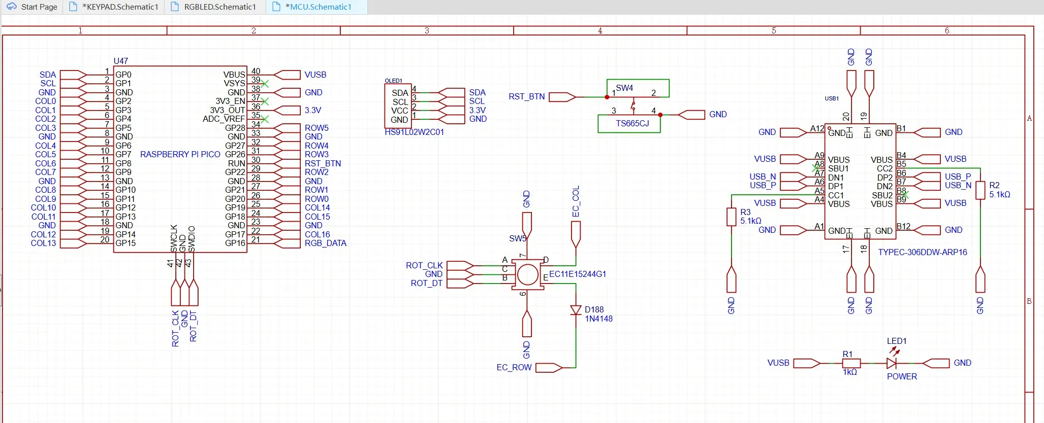
A reset button and a power LED are also added in the design.
PCB Design and Mechanical Layer Integration
Unlike conventional keyboard designs that use a single PCB and a separate metal plate, this keyboard was designed as a three-layer PCB structure, where each layer serves both a functional and aesthetic purpose. This layered approach allowed me to blend electrical design, mechanical structure, and visual storytelling into a single cohesive system.
The bottom PCB layer hosts all electronic components, including switches, diodes, RGB LEDs, the Raspberry Pi Pico, OLED display, rotary encoder, and USB Type-C connector. The second layer functions as the plate, providing mechanical support for the switches, while the third layer (top) acts as the frame, defining the overall shape and rigidity of the keyboard. Together, these layers form a stacked structure that is both structurally sound and visually expressive.
Switch Placement Workflow and Layout Accuracy
To ensure accurate and standard-compliant switch placement, I began the layout process using Keyboard Layout Editor (KLE) (https://www.keyboard-layout-editor.com/). I selected the preset ANSI 104-key layout and removed the numeric keypad to achieve the desired TKL configuration. Once the layout was finalized, I exported the row data and imported it into Swill’s Keyboard Plate Builder (http://builder.swillkb.com/).
The following is a screenshot of the layout editor.
The following is the screenshot of the plate generated from the raw data from the above layout:
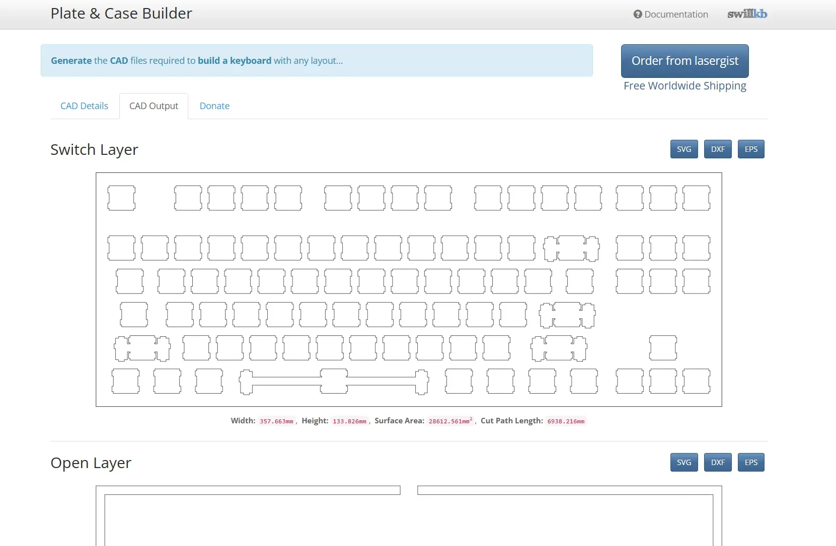
Using the Plate Builder, I generated precise DXF files for the switch layout and cutouts. These DXF files were then imported into EasyEDA, where they served as an exact reference for placing every key switch footprint on the PCB. This workflow ensured consistent key spacing, perfect alignment, and compatibility with standard mechanical keycaps, while also significantly reducing placement errors.
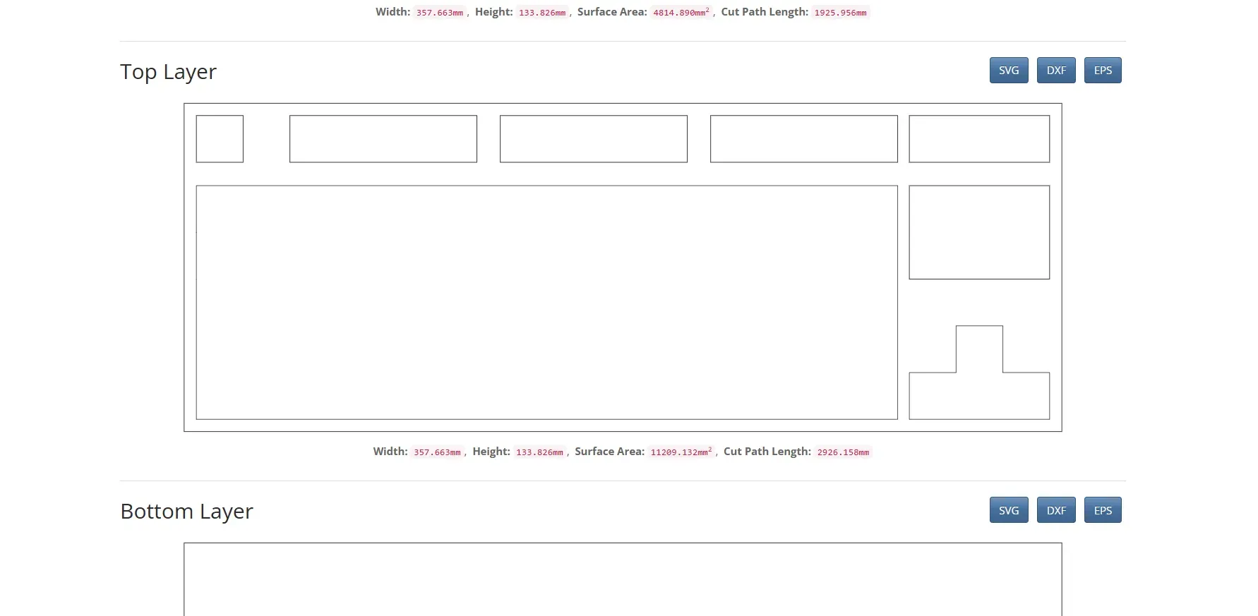
The following is the top layer generated from the swillkb builder site.
Watch The Video
Diode Placement as a Visual Design Element
Every key in the keyboard uses a dedicated diode to prevent ghosting, but instead of placing the diodes close to individual switches—as is commonly done—I intentionally treated them as a visual design feature.
All diodes were physically aligned into three straight, parallel diode rows, divided into three distinct sections across the PCB. This decision was made purely for aesthetic reasons, transforming an otherwise hidden electrical necessity into a visible design highlight. Care was taken to ensure that this arrangement did not negatively impact routing or electrical performance.
To further enhance this effect, I placed six additional addressable RGB LEDs within these diode sections—one LED on each side of every diode group. When illuminated, these LEDs frame the diode lines with light, emphasizing symmetry and creating a striking visual contrast against the PCB surface.
Controller, USB, and Peripheral Placement
To preserve a strong DIY identity and keep the design visually honest, the Raspberry Pi Pico was placed prominently on the right side of the PCB rather than being hidden. A matching window was added to the plate layer, allowing the Pico to remain fully visible after assembly. This design choice highlights the controller as the heart of the system and reflects the maker-friendly nature of the project.
A USB Type-C connector was placed in the top-right corner for modern connectivity and ease of access. Below the Pico, a 128×32 OLED display was positioned to present layer status and system information. Finally, the rotary encoder was placed in the bottom-right corner, providing intuitive physical control without interfering with the main typing area.
Each component was positioned with careful consideration of usability, routing simplicity, and visual balance, ensuring that the PCB remains clean, accessible, and aesthetically cohesive.
This PCB design reflects my belief that hardware does not need to be hidden to be beautiful. By intentionally exposing functional elements—such as diodes, LEDs, and the controller—and integrating them into the mechanical layers, the keyboard becomes a transparent expression of its own engineering.
The result is not just a working keyboard, but a layered, expressive hardware design that celebrates both function and form—true to the spirit of DIY electronics and embedded systems design.
After finalizing component placement and completing all signal routing, the PCB layout appears as shown below.
Top layer:
Bottom layer:
Following is 2D layout (base layer):
3D View of the bottom base layer:
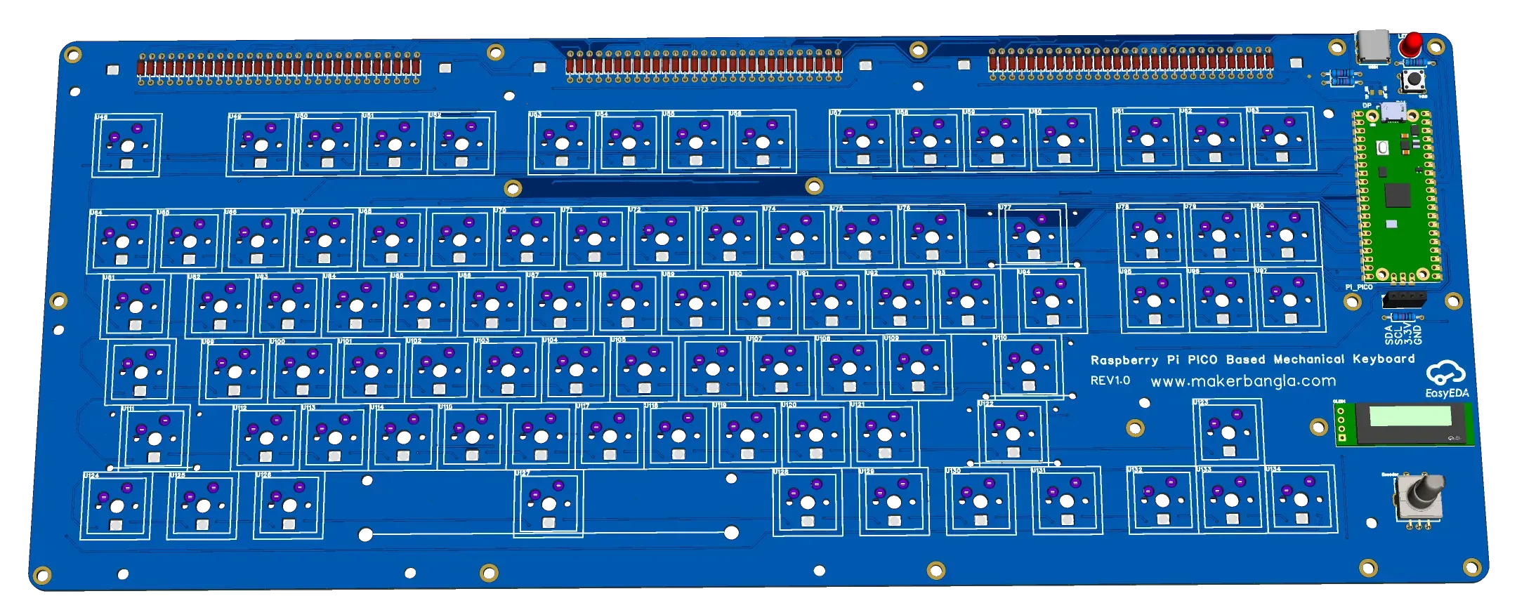
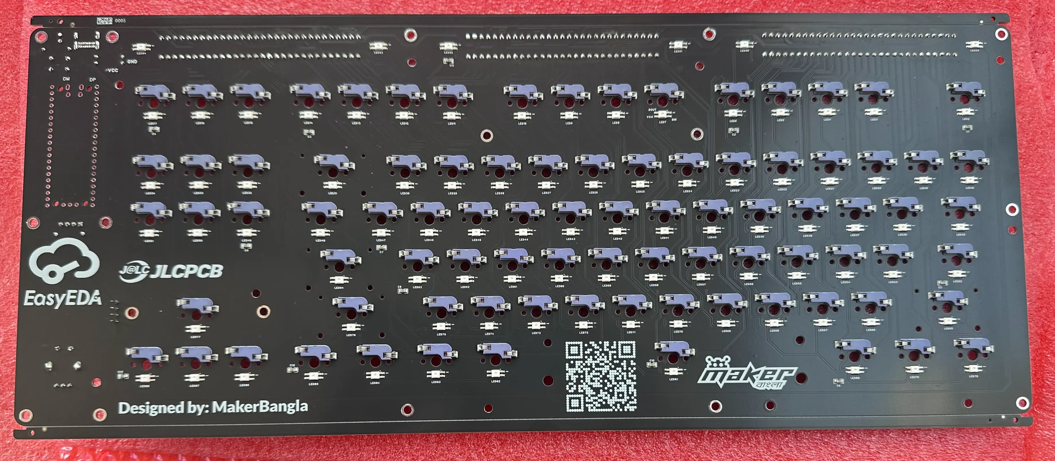
From the 3D view of the design, it becomes evident that the hot-swappable switch sockets and the RGB LEDs are mounted on the bottom side of the PCB. This placement was chosen to keep the top side clean while maintaining full functionality. Each RGB LED is aligned with a dedicated cutout in the PCB, allowing light to pass upward through the board and around the switch area.
This design ensures that the illumination is visible from the top of the keyboard without interfering with switch placement or routing on the main surface. The combination of bottom-mounted LEDs and precisely aligned cutouts creates a uniform lighting effect while preserving the clean and organized appearance of the PCB.
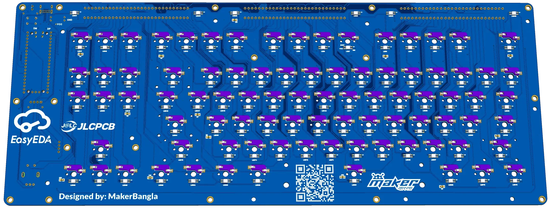
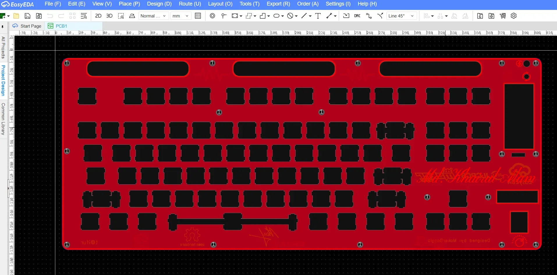
Plate and Frame Cutouts for Visual Exposure
To make the diode sections visible from the top, the plate and frame PCBs were designed with three dedicated window cutouts, positioned directly above the diode rows. These windows allow light from the LEDs to pass through while visually exposing the aligned diodes beneath.
PCB layout of the plate:
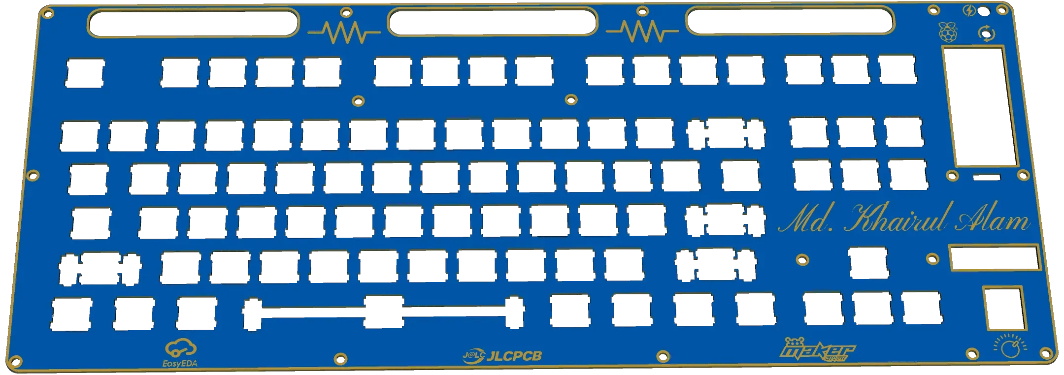
3D layout:
The following image shows the 3D layout of the plate layer. From the image, the three window cutouts for the diode sections are clearly visible, along with the dedicated window on the right side for the Raspberry Pi Pico.
When the keyboard is powered on and the LEDs on both sides of a diode section are illuminated, the effect is especially striking. The combination of exposed diodes, symmetrical lighting, and layered PCB depth creates a unique aesthetic that reinforces the idea of the keyboard as both an electronic device and a piece of functional PCB art.
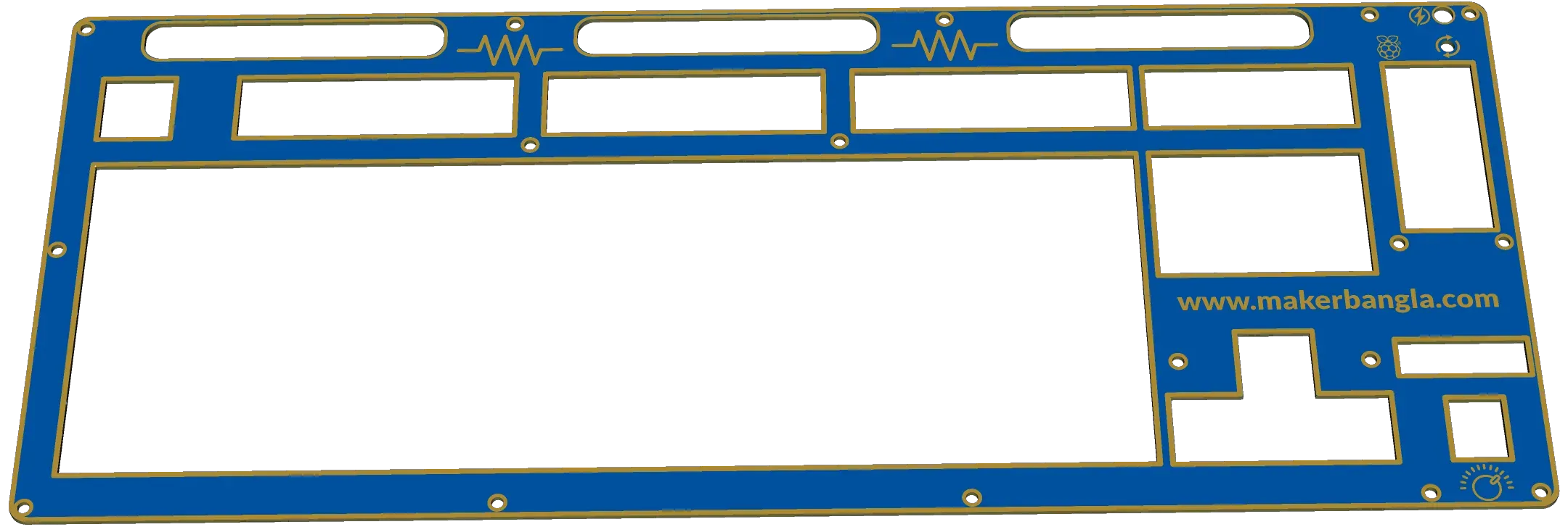
The following is the 3D view of the frame layer of the keyboard.
All three layers of the design were initially integrated within a single EasyEDA project to ensure proper alignment and consistency across the PCB, plate, and frame layers. This approach made it easier to verify component placement, cutouts, and mechanical clearances during the design phase.
Before ordering the PCBs, each layer was separated into its own individual project by deleting the other layers. This step was necessary to generate independent fabrication files for the PCB, plate, and frame, allowing each layer to be manufactured according to its specific requirements.
Designing all three layers with PCB material ensures exceptional accuracy, durability, and ease of manufacturing since they can be fabricated together using the same PCB production process. This approach also allows unique visual effects, such as color-matched layers and integrated backlighting, making the keyboard both functional and visually striking. It’s a perfect example of how PCB technology can go beyond electronics to shape the entire mechanical and aesthetic design of a custom keyboard.
Ordering the PCB
After completing all design steps and verifying the layout using Design Rule Check (DRC), the PCB was ordered directly through the Order menu within the EasyEDA design tool.
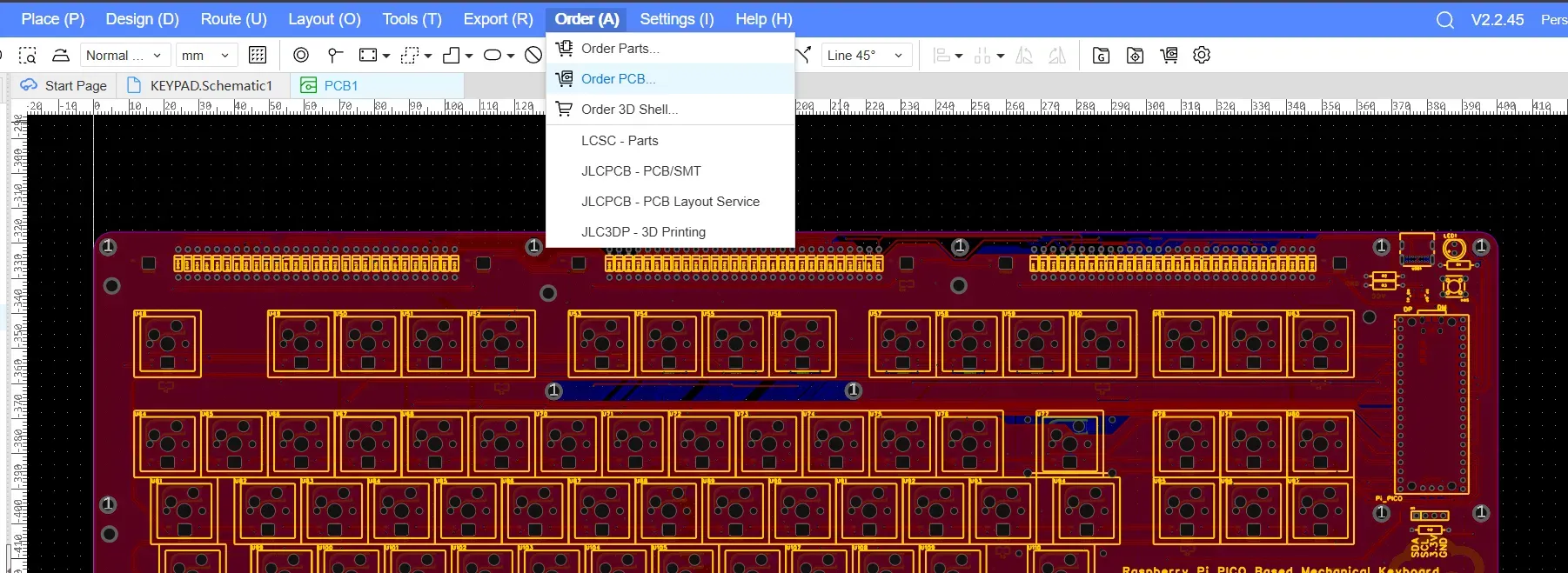
EasyEDA redirects the design directly to JLCPCB, where fabrication parameters such as PCB quantity, board color, thickness, and surface finish can be selected before placing the order. This seamless integration simplifies the manufacturing process and reduces the chance of errors during file transfer.
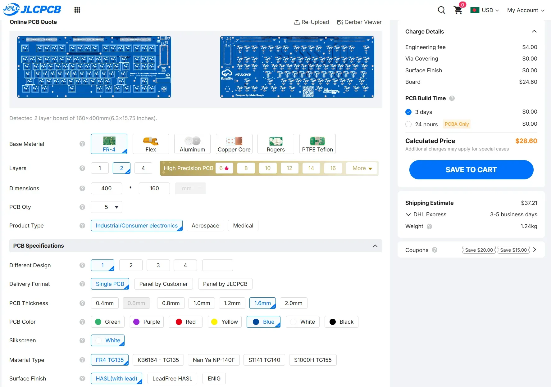
In addition to PCB fabrication, JLCPCB also offers an optional PCB assembly service, which can significantly reduce the effort required to source components from multiple suppliers and solder them manually. By using the assembly service, components are placed and soldered professionally, ensuring consistent quality and saving a substantial amount of time—especially for designs with a large number of components such as RGB LEDs and diodes.
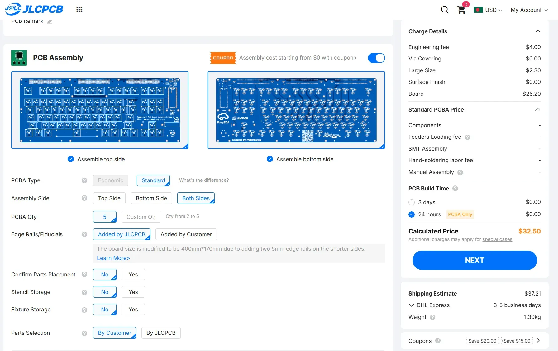
Overall, the combination of EasyEDA and JLCPCB provides a convenient, reliable, and maker-friendly workflow, allowing designers to move efficiently from schematic to a fully manufactured and assembled board with minimal friction.
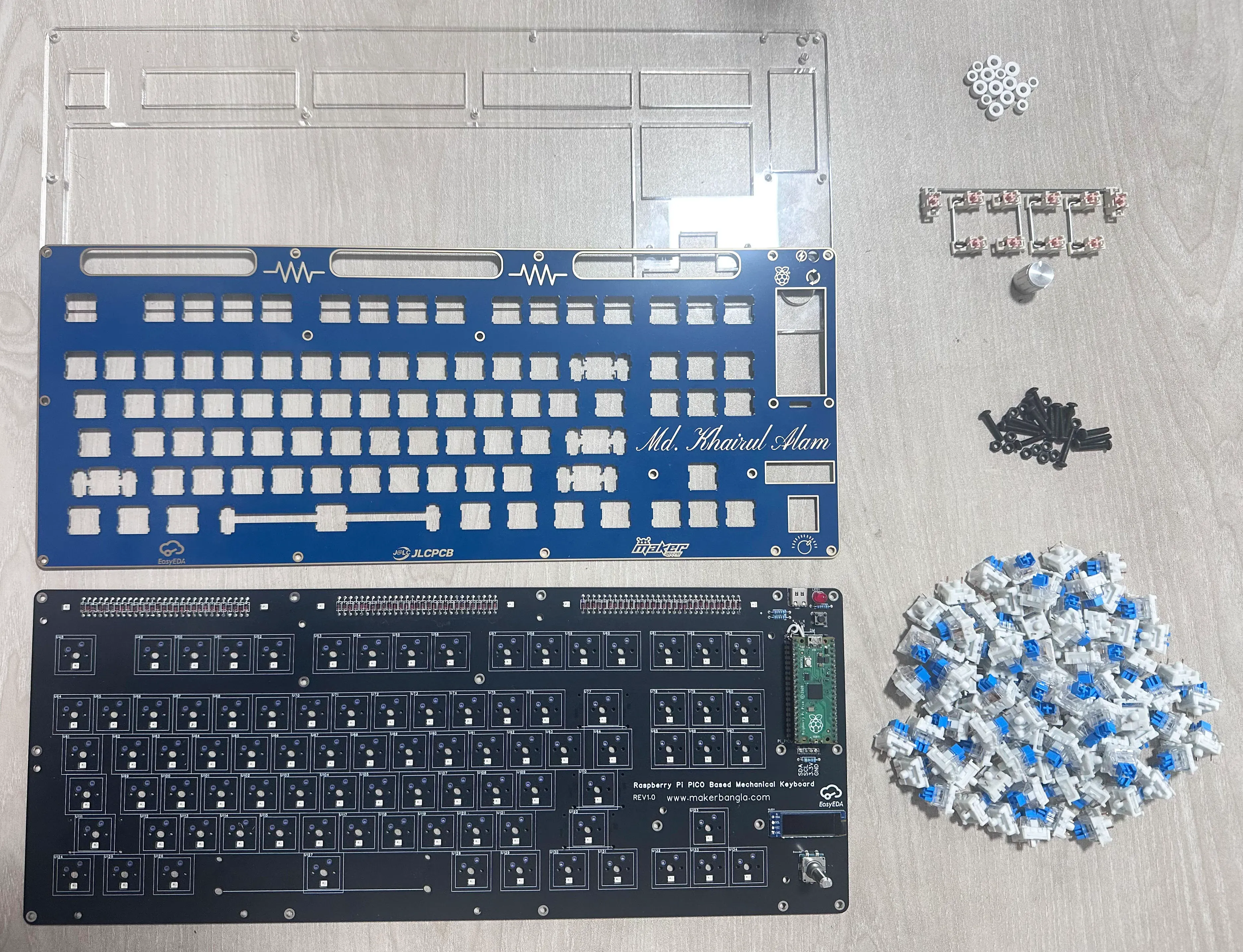
Collecting the Necessary Components
While I was waiting for the PCB I collected the following components for finishing my mechanical keyboard.
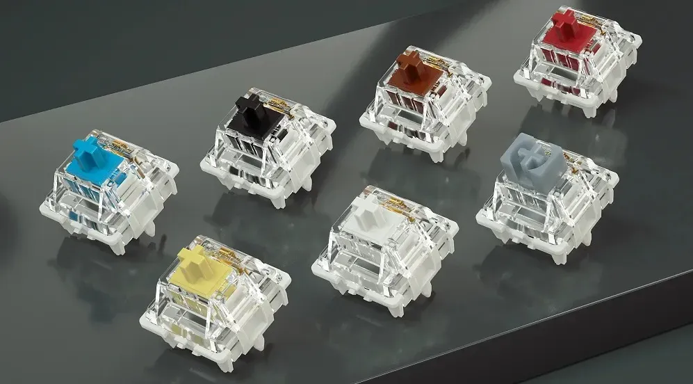
1. GATERON G Pro V3 3.0 Pro Switch (you can choose Clicky or Tacktile or Linear as yor preference)
2. Keycap Set (Totally depends on your choice)

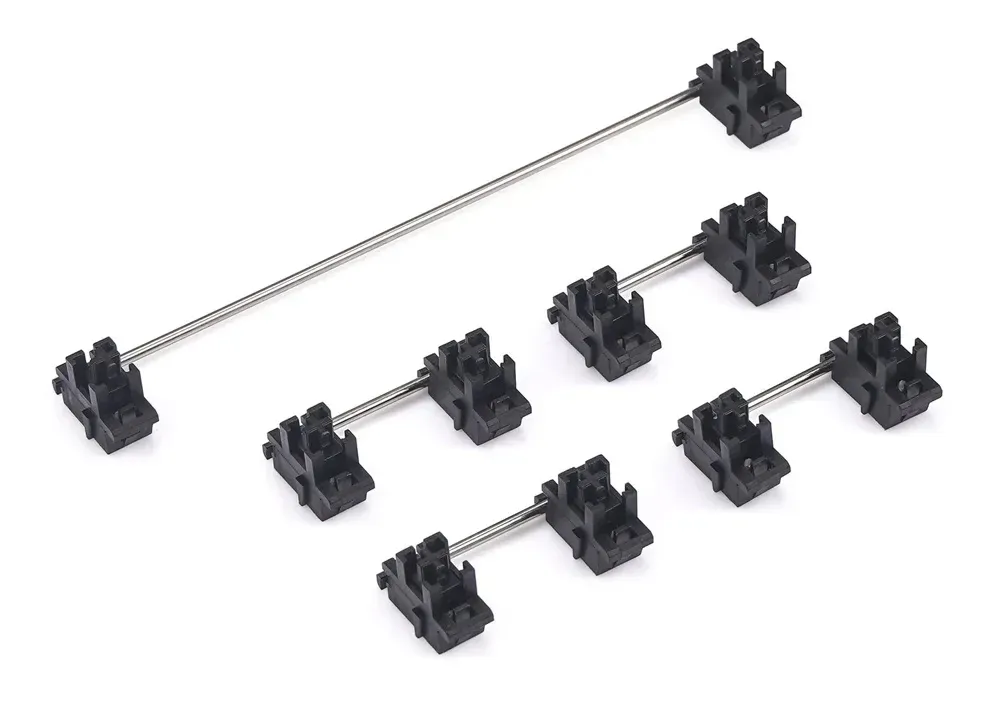
3. Stabilizer for Mechanical Keyboards (you can choose PCB-mounted or plate-mounted)
4. Rubber O Ring Keyboard Switch Dampeners (Optional)

5. 4mm M3 Spacer (hex or round)

6. Aluminum Knobs for Rotary Encoder

7. Official Raspberry Pi Pico Board (with header)
8. M3 Screw and Nut (12mm and 16mm)

Required Tools:
1. Soldering Iron (generic)

2. Wire Cutter (generic)

20 days later ....
After a 20-day wait for PCB fabrication and assembly, I finally received the boards—delivered with impressively cool and professional packaging.
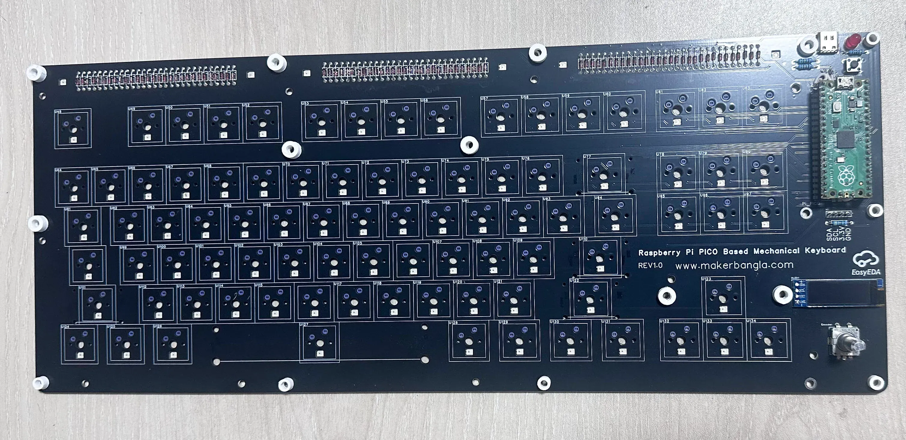
The following are the top and bottom sides of the base PCB.
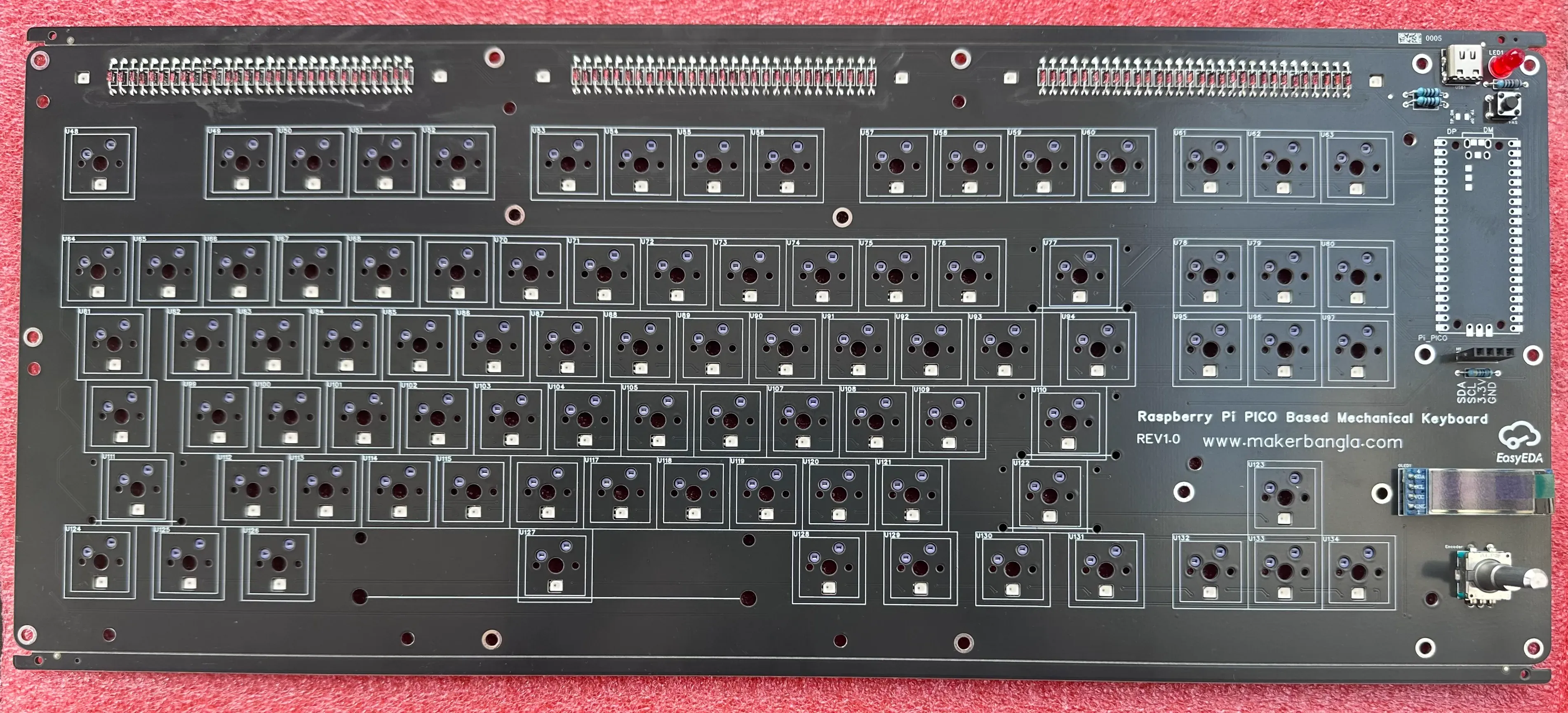
I chose black as the PCB color for my mechanical keyboard because it complements the per-key RGB lighting both functionally and aesthetically. A black PCB absorbs stray light and minimizes unwanted reflections, allowing the RGB LEDs to appear brighter, more vivid, and well-defined under each key. This enhances color contrast and improves the overall visual clarity of the lighting effects.
I was extremely pleased with the overall PCB quality, particularly the assembly and soldering, which were done with great precision. The silkscreen text was sharp and clearly legible, reflecting a high standard of manufacturing and attention to detail.
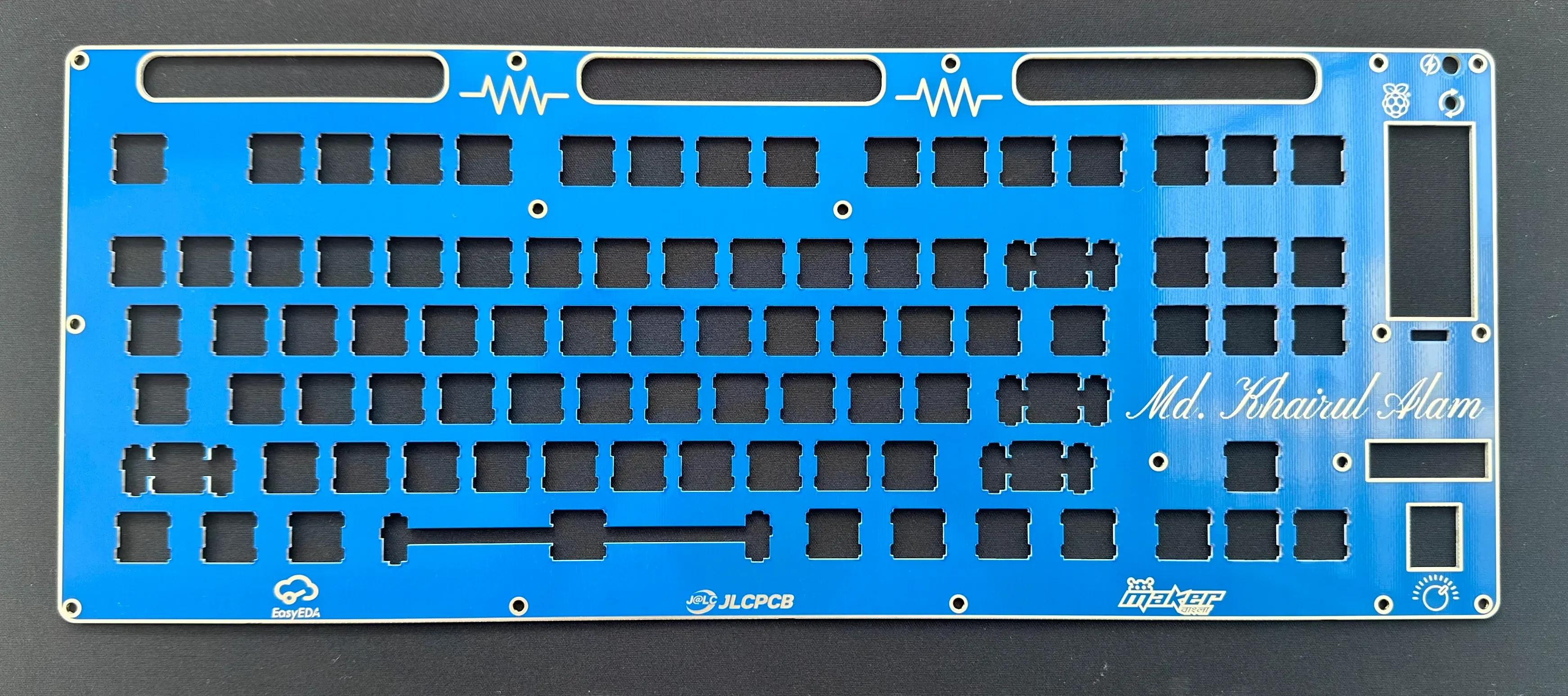
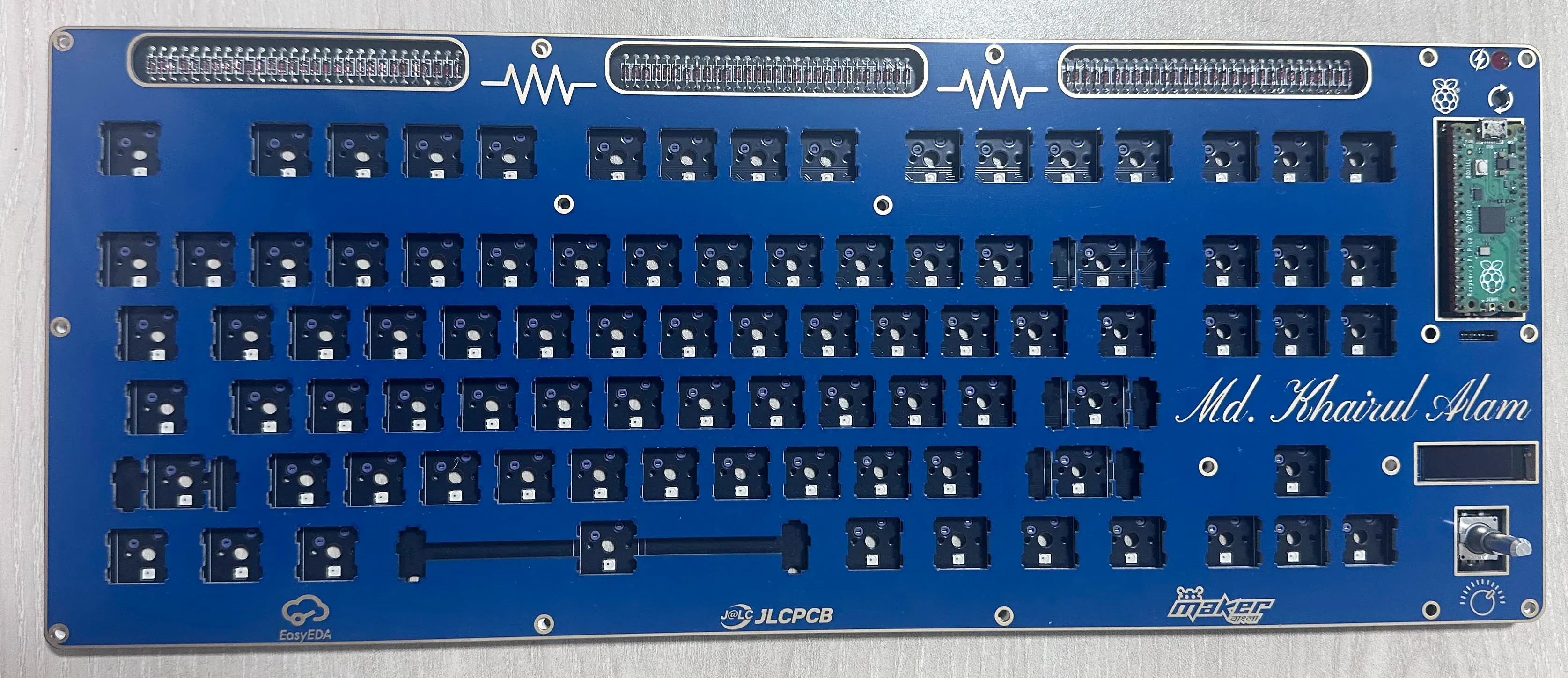
The following is the key switch plate with an attractive blue color. This can be used as a middle layer if you want to use a frame layer, or it can be the top layer:
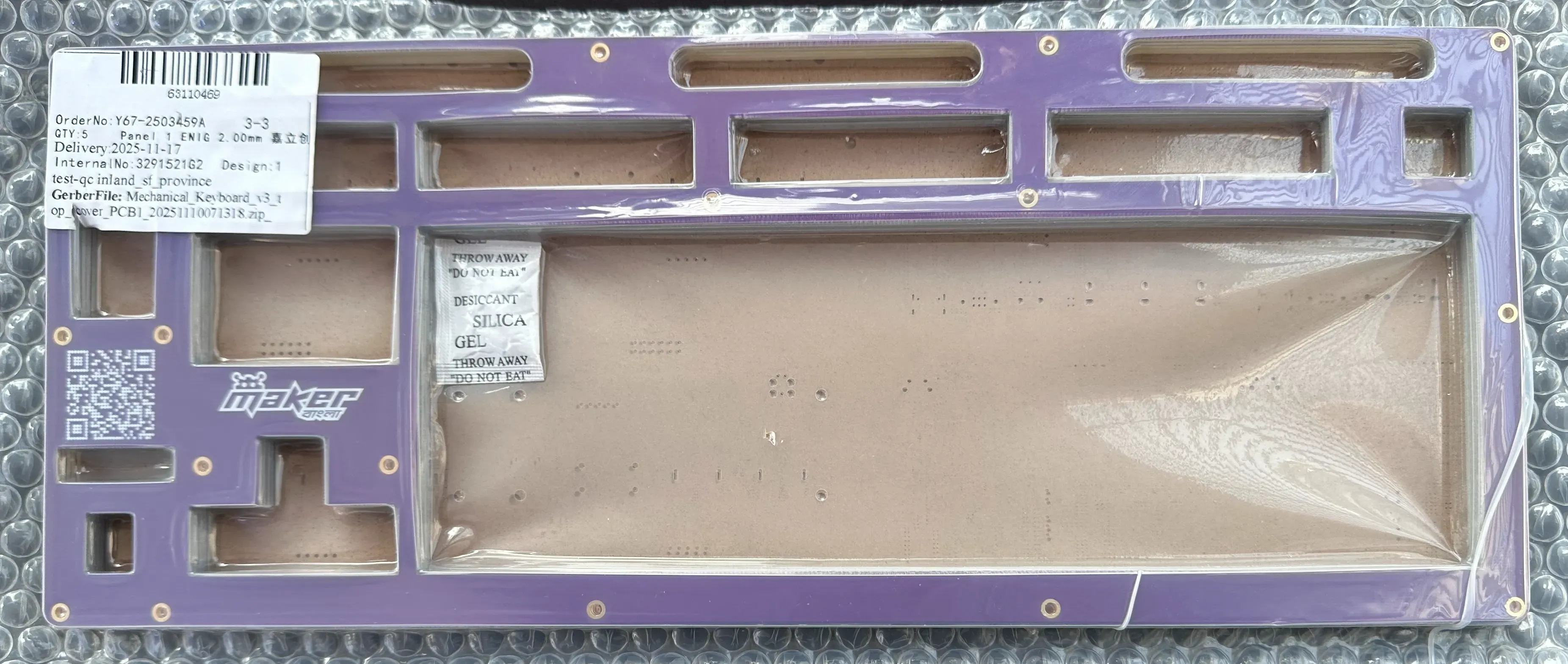
The following is the optional frame layer if you want a PCB frame for your keyboard. I made it purple. (this is the bottom layer)
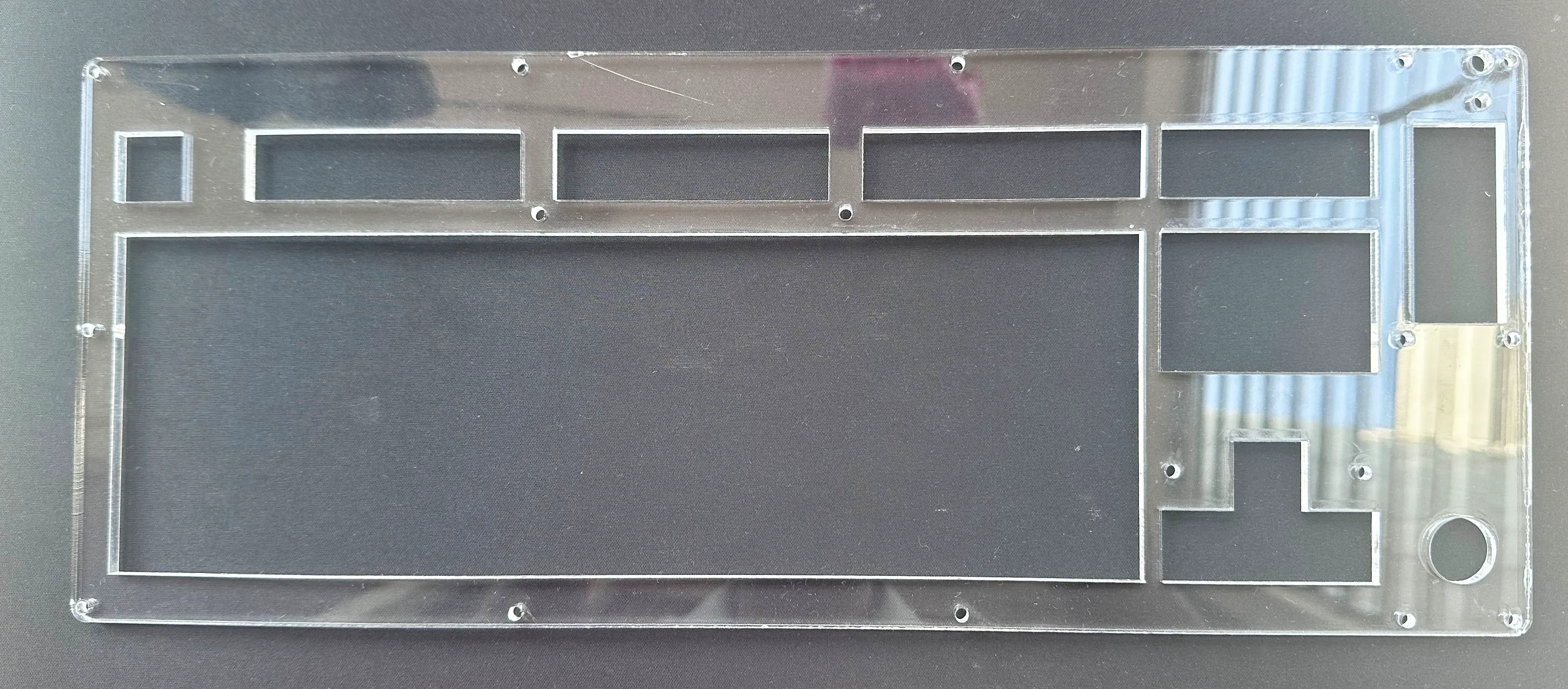
For the top frame of my mechanical keyboard, I used a 5 mm thick acrylic sheet. I cut the acrylic according to the exact frame measurements using a laser cutter, which allowed it to precisely cover all the window cutouts while protecting the switch plate and giving the keyboard a clean, professional finish.
Assembling the Keyboard
I now have all the necessary components in hand, so it’s time to start assembling the keyboard.
Step 1. I soldered two 20-pin female headers onto the base PCB to mount the Raspberry Pi Pico, as shown in the image below.
Step 2: Next, I placed 4 mm spacers on top of each screw hole, as shown in the image below.
Step 3: After that, I placed the plate PCB on top of the base board shown in the image below.
Step 4: I installed the stabilizers onto the plate PCB, as shown in the image below.
Step 5: Then, I placed the acrylic sheet on top of the plate.
Step 6: Then, I inserted all the screws to secure the base PCB, plate, and acrylic frame together.
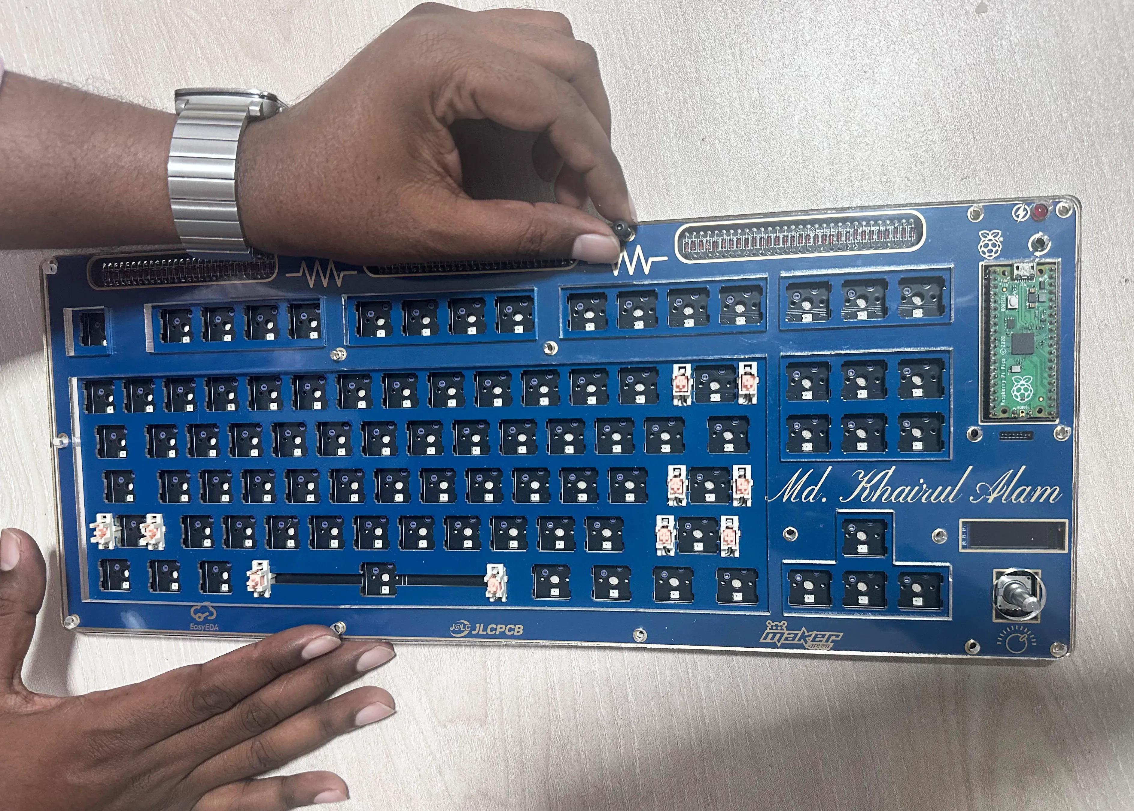
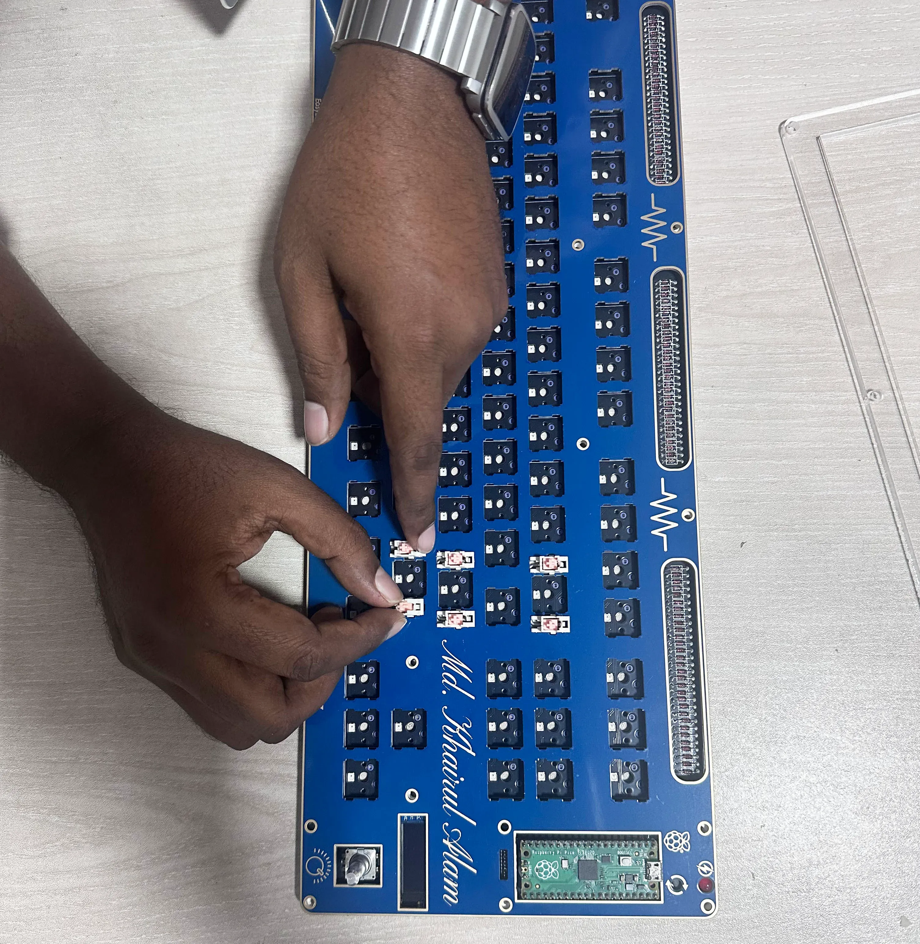
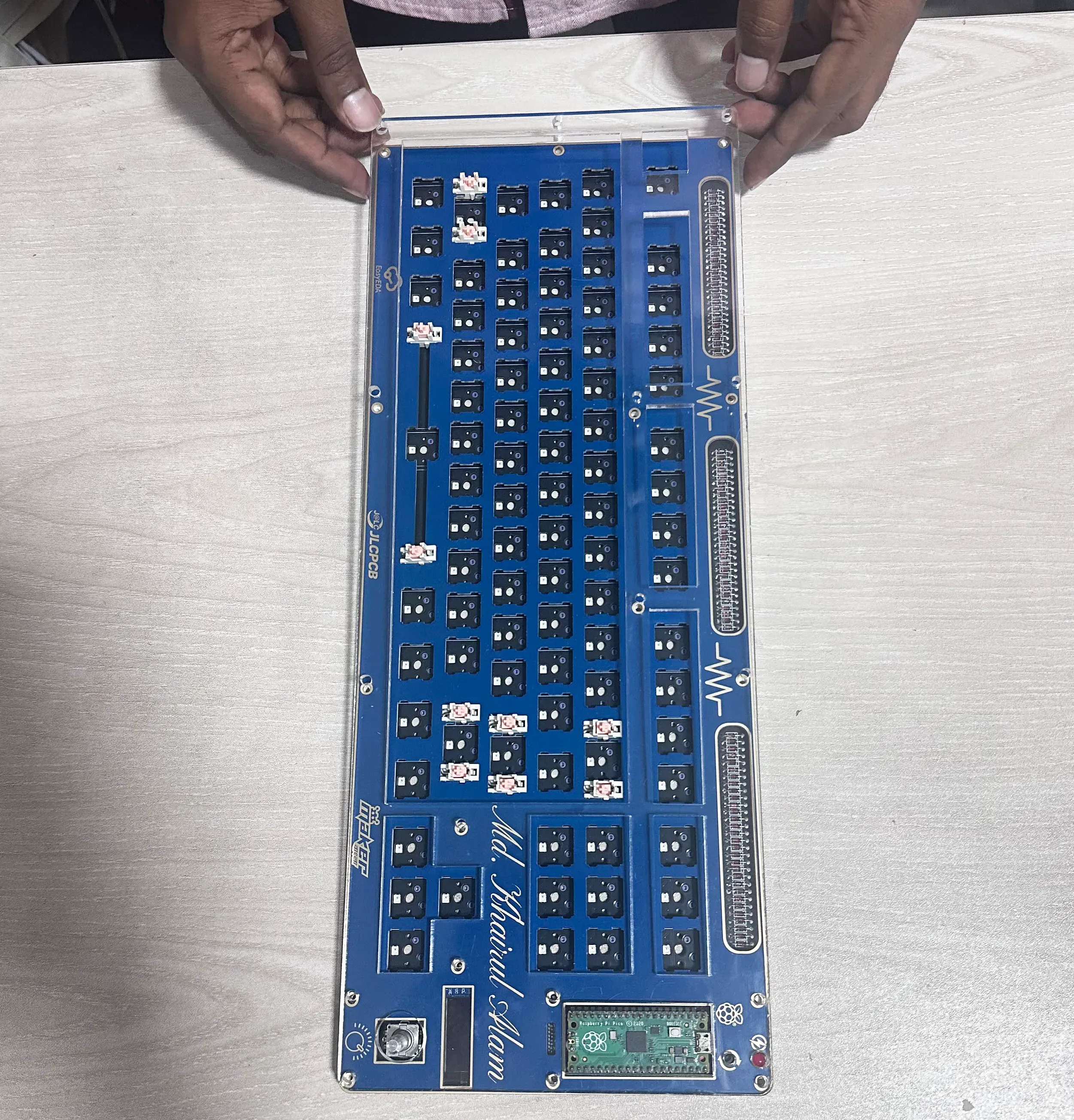
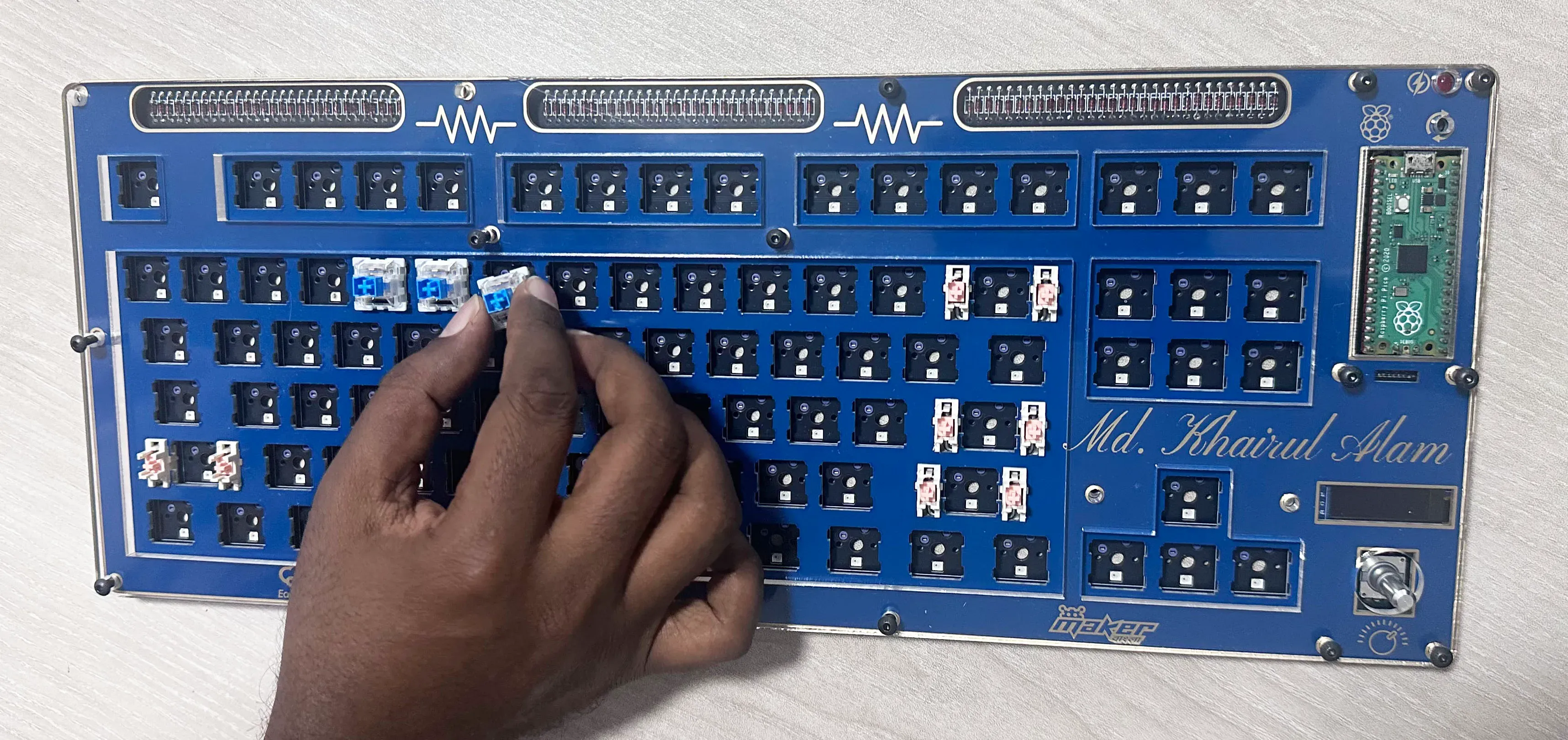
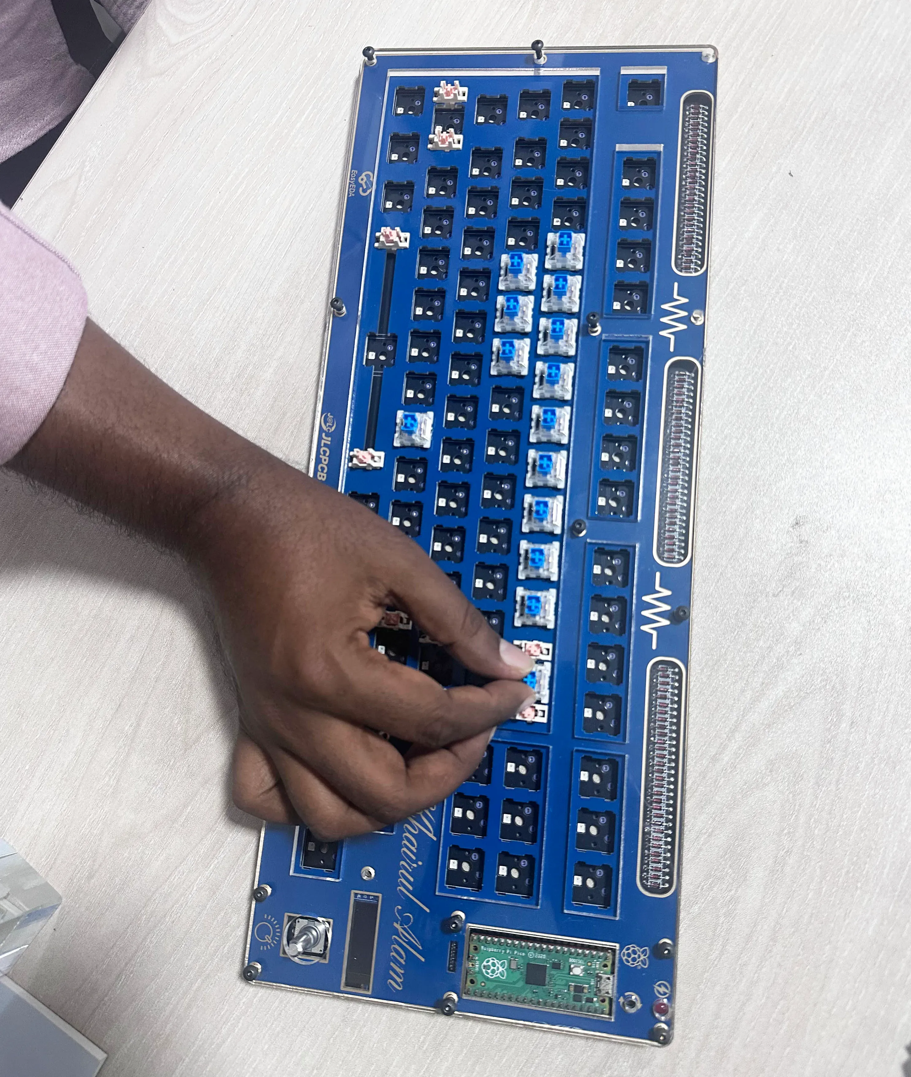
Step 7: At this stage, I carefully inserted all the switches into the PCB.
Developing the Firmware
The keyboard firmware was developed using the QMK (Quantum Mechanical Keyboard) firmware library, an open-source and widely used platform for custom mechanical keyboards. QMK provides a flexible framework to define keymaps, layers, and advanced features such as macros, RGB lighting control, rotary encoders, and custom behaviors.
Using QMK, I configured the keyboard layout, assigned functions to each key, and enabled OLED screen, allowing it to display real-time information, and to control the rotary encoder. The firmware was compiled into a UF2 file and flashed onto the Raspberry Pi Pico, allowing the keyboard to function reliably with full customization support. One of the main advantages of QMK is that it makes future changes—such as remapping keys or adding new features—easy without modifying the hardware.
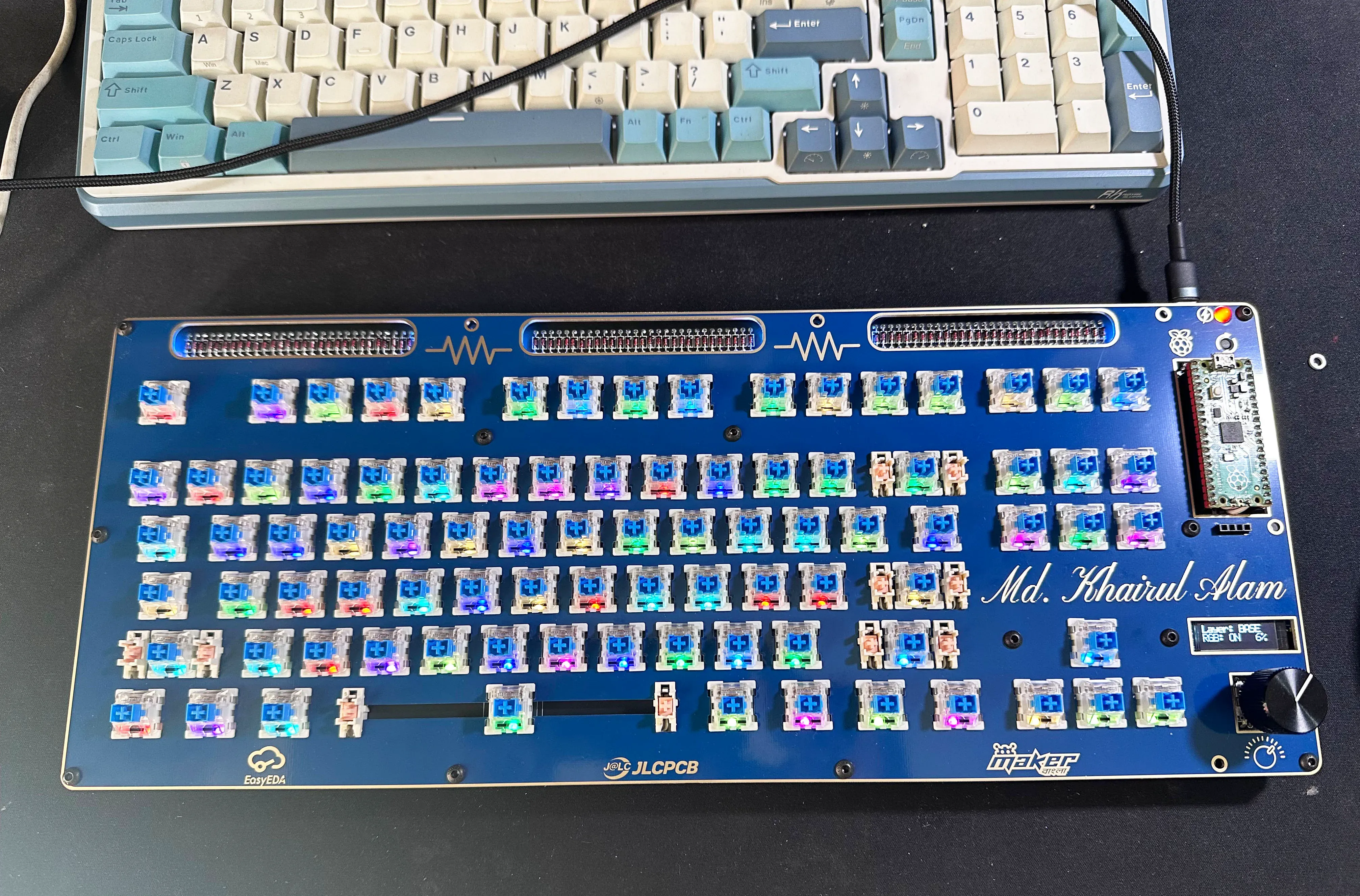
The following image shows a key stage of the firmware development process, where I successfully initialized and controlled both the RGB LEDs and the OLED display. At this point, the keyboard was able to light up with customizable RGB effects while the OLED screen displayed real-time information, demonstrating that the firmware was correctly communicating with and managing the additional hardware components.
The complete firmware is available on my GitHub: https://github.com/taifur20/pico_tkl
The prebuilt firmware is already uploaded. If you follow my complete design without any modifications, you can directly flash the firmware. However, if you make any changes to the schematic or PCB layout, you will need to update the firmware accordingly and recompile it before uploading.
If you want to recompile, please follow the guidelines here: https://docs.qmk.fm/newbs
Finished Keyboard
Video is coming soon....
Design Drawing
BOM
 Clone
CloneProject Members
 Empty
Empty
Comment