

 Completed
LED CLOCK- AIO v1.3_PRO
License
:MIT License
Description
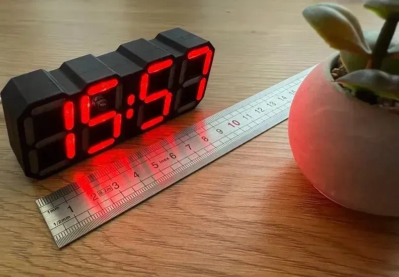
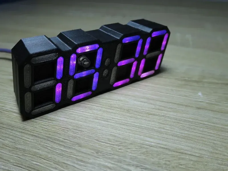
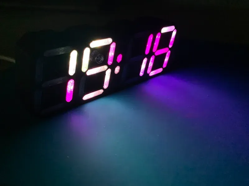
Led Clock - AIO
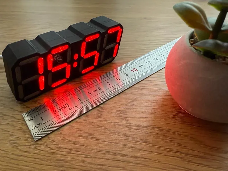
This version features an ALL IN ONE (AIO) approach for the ledclock project by imeszaros.
You can find the GitHub repository here: https://github.com/mariusmym/LedClock-AIO
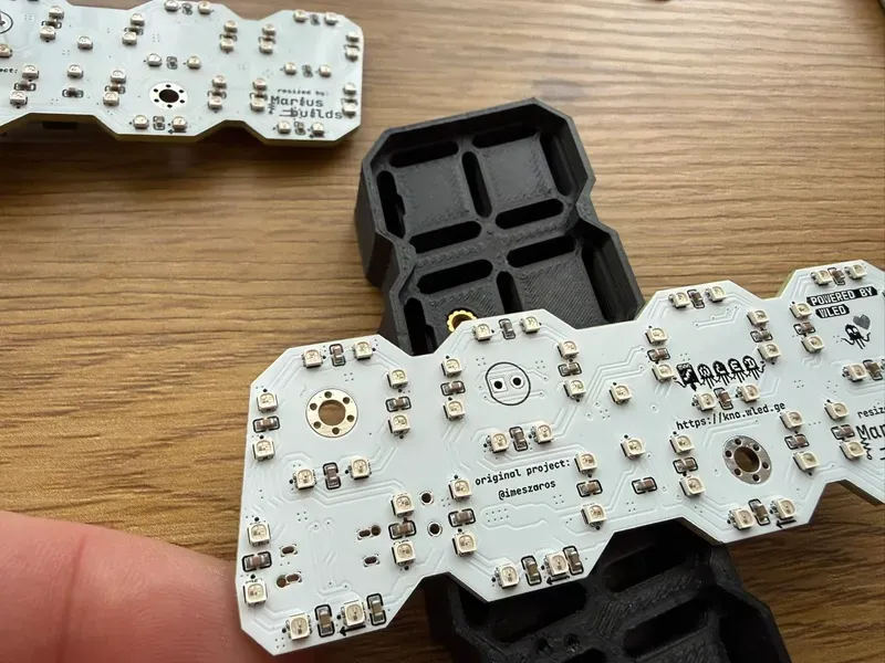
The PCB was specifically designed to be under 100mm so it will cost less to produce it.
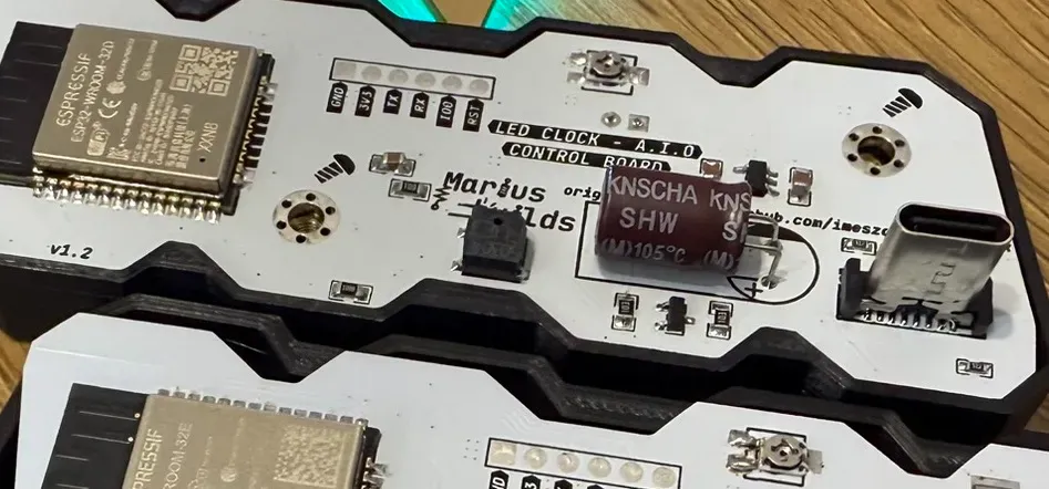
The board is powered via a USB-C cable.
All the components can be soldered by hand, some of the footprints are modified to allow this, but I still recommend you to order a stencil as well, at least for the FRONT of the PCB (where the LEDs are), because otherwise is gonna be quite hard (and time consuming) to hand solder all those LEDs.
You can also use WS2812B-2020 LEDs which are a bit more expensive, as well as TCWIN TX1812ZN (which are a little bit bigger), but keep in mind that you have to double/triple check the pin orientation since the silkscreen marks doesn't match.
Assembly instruction and tips
After completing the top-side assembly, proceed with the bottom side.
Please pay special attention to the photoresistive sensor: it must be soldered 5–7 mm above the top layer of the PCB so that it protrudes through the case.
Also note that the C3 (1000 µF) capacitor must be mounted horizontally, as shown in the image below.
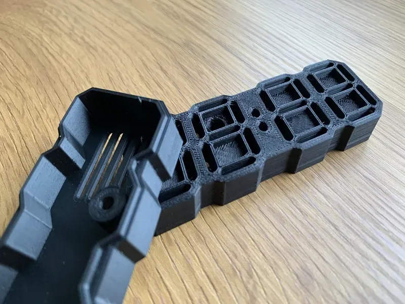
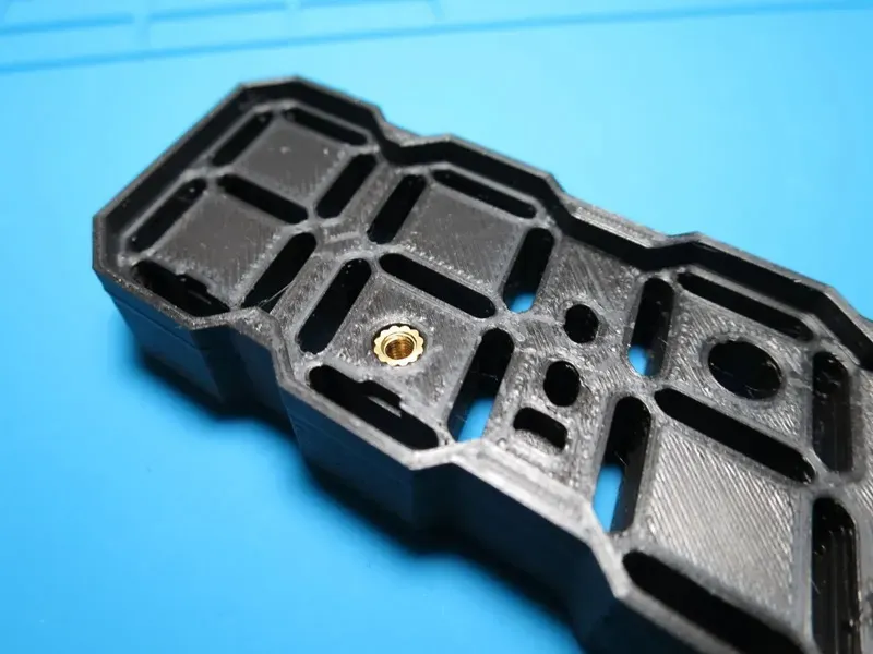
Print the case files from the CaseModel folder of this repository in the colours that you like. You can also find the files here: https://www.printables.com/model/1087560-led-clock-all-in-one-pcb-powered-by-wled
You will also need two M3 heat inserts and two M3x8mm CSK screws.
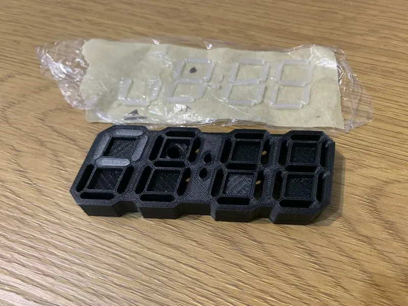
Segment covers need to be printed with a transparent filament, 20-30% infill, and 2-3 top/bottom layers. Depending on your printer accuracy you might want to print the offset segments file (which are 0.1mm smaller) .
In order to keep track of them I place a masking tape over them before removing them from the plate and then place piece of kitchen stretch film over the tape.
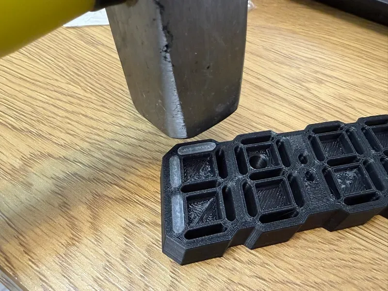
If the tolerances are too tight and you have problems inserting those segments cover, you can use a small hammer to "tap" the segments a little bit :)).
Firmware is provided by the awesome work of imeszaros.
Just connect the Led Clock onto the computer (be sure you have CH340 drivers installed) and use this tool to flash the board (be sure to select de proper COM port).
Download the WLED app from your phone's store and connect the clock in order to change the colors.
- Google Play: https://play.google.com/store/apps/details?id=ca.cgagnier.wlednativeandroid
- Apple App Store: https://apps.apple.com/us/app/wled-native/id6446207239
A detailed guide can be found here https://github.com/imeszaros/ledclock/blob/main/ledclock/users-guide.md
ENJOY !
Design Drawing
BOM
 Clone
CloneProject Members
Intellectual Property Statement & Reproduction Instructions
This is an open-source hardware project. All intellectual property rights belong to the creator. The project is shared on the platform for learning, communication, and research only; any commercial use is prohibited. If your intellectual property rights are infringed on EasyEDA, please notify us by submitting relevant materials in accordance with the Rules for Complaints and Appeals of IPR Infringement.
Users must independently verify the circuit design and suitability when replicating this project. All risks and consequences are borne by the user, and the platform assumes no liability.
 Empty
Empty
Comment