

 Completed
Wireless Boot Button
PRO Wireless Boot Button
License
:GPL 3.0
Description
#Disclaimer# Installation and use require certain hands-on skills and knowledge. Wrong installation and use (including but not limited to short circuit, electrostatic breakdown, wrong connection, miracles caused by force...) may make your motherboard say goodbye to you forever. , I will not be responsible for your motherboard.
B station video: https://www.bilibili.com/video/BV1ke411f7Ny/
1. Description
1. Wireless power on button based on Hummingbird T5A and R5A modules.
2. Ultra-low power consumption, only 0.06mA, onboard antenna.
3. Frequency: 433MHz.
4. The module does not require development and can be used after the welding is completed and coded.
5. There are multiple versions of both TX and RX terminals, you can choose according to your preference.
2. Project Introduction
TX side version ①: The TX side uses the Gaote 4x axis as the switch and uses two AA batteries or cr2032 for power supply (choose one of the two). The power consumption is very low. In theory, two AA batteries can be used for several years. . See the physical display chapter for actual pictures.
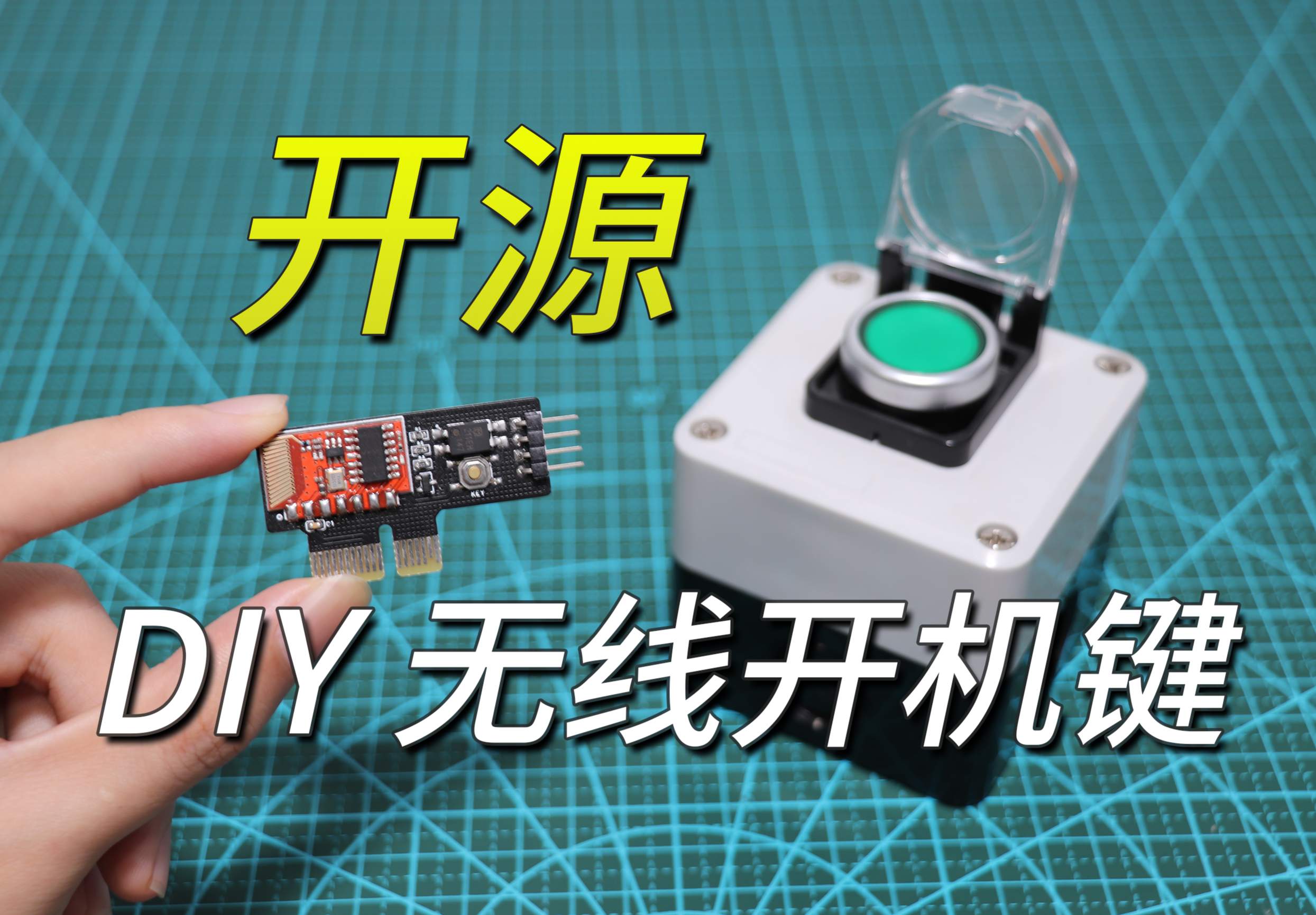
TX version ②: Considering that the current price of Gaote 4x axis is relatively high, printing the shell and keycaps is a big expense (for students who do not have a 3D printer). So a low-cost button (pictured below) alternative was made.

The RX side has a variety of interface modes. Currently, PCI and PCI-E x1 have been produced. In the future, USB2.0 9pin interface or motherboard 5v/3.3v power interface is planned.
The PCB is very compact and has two sets of power-on jumpers. The wireless power on button and the chassis power on button can be used at the same time . The wiring method uses DuPont wire.
Both the RX and TX ends are on-board antennas. According to actual measurements, the signal reception is very sensitive when there is no obstruction. However, there is a small probability that it will not trigger when there are obstacles (installation of iron side panels and desktop obstructions), so the glass side is more recommended. board chassis, and users who place the chassis on the desktop.
The reason for non-triggering may also be signal interference, false soldering, power supply, etc. Perfectionists reproduce with caution.
Please check for problems by yourself when re-engraving. If there are any errors in my schematics or PCB or if you have better suggestions, please contact me in time.
3. Update Log:
2023/01/30
The keycaps and shells have been prototyped and tested.
2023/02/01
Industrial button PCB verified.
2023/11/05
Updated text description.
There are plans to make a spring antenna version in the future.
4. Installation Instructions:
If the keycap is too loose, apply a thin layer of glue and wait for the glue to dry before installing it. If it's still loose, repeat again.
The upper cover adopts hot melt clay nuts. For specifications, please purchase according to the BOM table in the attachment. Use a soldering iron at around 250°C to embed. The embedding process should not be too fast and press at a constant speed. FDM printing is recommended for the upper cover. Light-cured resin is relatively brittle and not suitable for hot-melt nuts.
After installing the screws on the lower cover, you can choose to attach round feet.
The connection between the shaft and the PCB is made of conductive tape . The shell can already fix the shaft well, so welding is not recommended (occasionally it can be removed for play). Friends with strong hands-on skills can use copper sheets bent into simple hot-swappable springs. Fixed to enable hot swapping.
The wiring for the industrial button version is connected to terminals 23 and 24.

5. Finished Product Display:


6.Suggestion:
It is recommended to use high temperature tape to protect the gold (tin) finger part when soldering. Before testing on the computer, use a multimeter to check whether there is a short circuit to prevent damage to the motherboard.
During autumn and winter, anti-static work should be done during welding, installation and use.
7.Test Video↓
Designed by morempty (from OSHWHub)
Link:https://oshwhub.com/morempty/ju-zhou-wu-xian-kai-ji-jian
Design Drawing
 Empty
Empty
Comment