

 Completed
TD3- Mobile pendant with wireless power supply
PRO TD3- Mobile pendant with wireless power supply
License
:GPL 3.0
Description
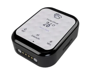
TD3-TouchDisplay3.0
A small charm based on ESP32-S3R8 and 1.89-inch QSPI screen, the experience is silky, and it also supports wireless charging and magnetic interface charging, onboard clock chip, six-axis gyroscope, pressure sensor, passive buzzer, etc., and supports SDMMC memory card file system.
 Early Bilibili introductory video
Wireless power delivery
Using Volta's NU1680 solution, it supports unlimited charging of up to 5W, basically the charging current will not exceed 1A through the charging speed limit of AXP173, and the peripheral components of 1680 have requirements for the material, it is recommended to refer to the manual to select the resistance and capacitance of the corresponding material.
Power management
Using the old scheme AXP173 chip, many students who have copied it say that this piece of custom voltage is too much to buy, and it can be modified into my open source single-cell lithium battery charging and discharging scheme, and you only need to write one more ADC acquisition scheme.
Buy 402530!! Buy 402530!! Buy 402530!! Buy something that doesn't fit and can't put it in.
Display screen
It is used in Huaxia Cai's 1.89-inch QSPI screen,The price is a little expensive, and there is no replacement for the current level,The most expensive hardware in the whole project is this screen,The IC of the screen is GC9B71Just this driver is in the IDF routine,Migration is very convenient,At the same time, it is also a routine with touch,The chip is also consistent,I don't want to use the code I provide to develop,You can try to migrate yourself.
Magnetically powered
The reason for choosing magnetic power supply is that it is very convenient to do the base design, and the model of the two components of magnetic power supply has been built, you can ask me if you need it.
Development configuration
1. Based on the 'ESP-IDF5.1.2' version, the IDF version may be replaced in the future.
2. 'lvgl' version is '8.3.11', may be upgraded to '9' in the future.
Environment configuration
The pulled code does not contain the '.vscode' folder, you need to open an idf sample project, and then copy the .vscode folder to the root directory of the project, or add it directly by the idf plugin.
Target board configuration
1. Set the current target board:
Project file structure description
│ ├─i2c // I2C driver
Flash download tools (bin file burning is not required, please ignore)
4. Manually shut down and restart after burning.
Introduction to page management framework
This page management framework is ported from the old TD3-App project, the original project is based on the Arduino platform, so it uses C++, but idf is C, although IDF supports C++ mixing but it is too troublesome to change to C, and lose the class and namespace.
How to add a page
1. Create a new page folder in the 'main\View\Pages' directory, which contains xxx.c files and xxx.h files, and xxx is your page name.
The .c file needs to follow the standard template as follows:
#include "Setting.h"
PageType *Setting;static void Created(){
}
static void Update(void){}
static void Destroy(void){ if (lv_obj_is_valid(Setting->PageContent)) { lv_async_call(lv_obj_clean, Setting->PageContent); }}
static void Method(void *btn, int event){}
void Setting_Init(){ Setting = lv_mem_alloc(sizeof(PageType)); strcpy(Setting->name, "Setting"); Setting->show_status_bar = 1; Setting->BeforeEnter = NULL; Setting->Created = Created; Setting->Update = Update; Setting->Destroy = Destroy; Setting->Method = Method; Setting->PageContent = create_new_screen(); Page_Register(*Setting);}Just replace all the 'Settings' in the file with other names.
.h file is relatively simple, also replace all the settings with your own, and then change the uppercase settings in the conditional compilation.
#ifndef SETTING_H#define SETTING_H
#ifdef __cplusplusextern "C" {#endif
#include "Page.h"void Setting_Init();#ifdef __cplusplus} /*extern "C"*/#endif
#endif
Preferably the title is black-modulated text content
1.Battery InformationGyroscope, Barometer, Memory Card, Real-time Clock, System Settings, Network Information, Weather Query, Music, Bluetooth, Buzzer, Configuration, Serial Port Data, Host Computer Monitoring, Connection, Disconnection Terminal.
2.Modify 'main\CMakeLists.txt' to add ''View/Pages/xxx'' where xxx is your page directory name, as for why not write a unified cmake file that needs to follow the IDF project standard, it will not be real-time, yes is "no".
Designed by AaronChu (from OSHWHub)
Link:https://oshwhub.com/aaronchu/td3-mobile-small-pendant-with-wi
Design Drawing
 Empty
Empty
Comment