

 Completed
Portable oscilloscope - main body part
PRO Portable oscilloscope - main body part
License
:LGPL
Description
1 Related links
Bilibili Easy Test Video Link: Graduation Project - FPGA-Based Portable Oscilloscope (Simple Demonstration) _ Bilibili _bilibili Bilibili test video (edited by colleagues): FPGA-based portable oscilloscope - waveform generation function demonstration _ Bilibili _bilibili Portable Oscilloscope - Display Module: OSC_panel - Lichuang EDA Open Source Hardware Platform ( oshwhub.com ) Portable Oscilloscope - Extended Data Acquisition Module: DSO_module - EDA Open Source Hardware Platform ( oshwhub.com )
Links to references: https://pan.baidu.com/s/1yL8x0anwPYvNF2imFU6t_g?pwd=p6pa
Extraction code: p6pa
RTL code link: https://pan.baidu.com/s/1mmWb2291aS75lud4RXpGvA?pwd=78sc
Extraction code: 78sc
Schematic diagram, PCB directly click on the upper right corner editor to open~~~
Welcome to like, coin 🤣🤣
2 Performance indicators
The oscilloscope part uses two AD9288s (dual 8-bit 100M sampling rate ADCs), and uses alternating sampling to enable the oscilloscope to achieve a maximum sampling rate of 400Msps for a single channel and 200Msps for a dual channel.
The waveform generator uses 3PD5651 with a conversion rate of 125M, a data bit width of 10 bits, and a maximum sine wave output of 20MHz. The output of the waveform generator can be directly connected to the oscilloscope section through a double-headed BNC cable for oscilloscope testing.
3 Module division
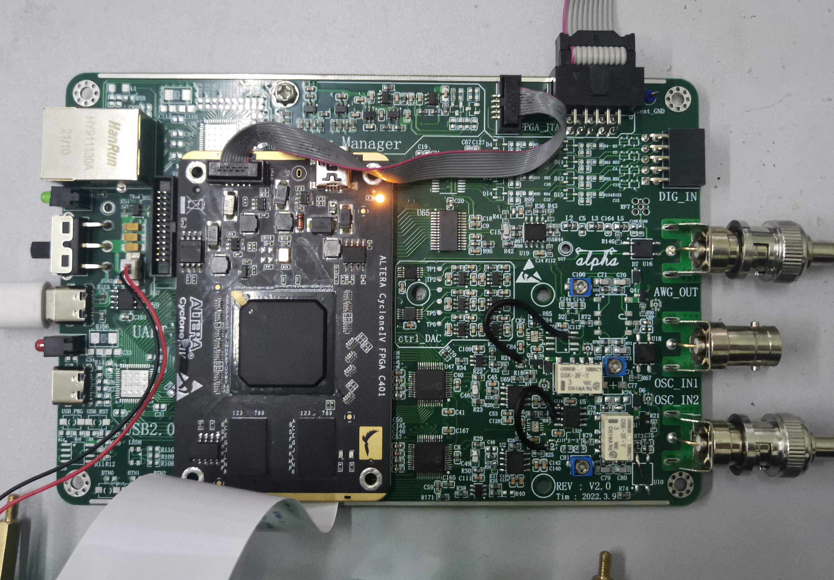
The hardware part of the system consists of FPGA core board, portable oscilloscope baseplate, portable oscilloscope display board, and extended Data Acquisition module.
FPGA Core Board: Logic Function Implementation (Altera FPGA Cyclone IV EP4CE30);
Portable oscilloscope baseplate: preprocessing waveforms and generating arbitrary signals.
Portable oscilloscope display panel: Combining functions and directional buttons to achieve different operations, LCD displays information.
Expand Data Acquisition Module: Expand the AD9288_ADC module, and the analog front-end circuit is the same as the baseplate.

4 Project Pictures


Designed by Alpha-go (from OSHWHub)
Link:https://oshwhub.com/Alpha-go/a5IITjkVGF1cA9kyTV2V9sIHra7GcIg2
Design Drawing
 Empty
Empty
Comment