

 Completed
[ Magic triangle ]M18- Bluetooth speaker
PRO [ Magic triangle ]M18- Bluetooth speaker
License
:GPL 3.0
Description
Project Background
In the era of pursuing high-quality audio experience, Bluetooth speakers are deeply loved by the public as a portable and practical audio playback device in life. In order to allow students to better learn and understand the knowledge of electronic circuits, master the skills of industrial design and intelligent product development and practice, and learn some interesting and practical and educational projects, the M18 Bluetooth speaker is a good choice. Most of the circuits are packaged in plug-ins, which are inexpensive and easy for novices to solder, making them suitable for teaching.
Project parameters
- The speaker is based on MH-M18Bluetooth5.0 chip,The chip comes with left and right channel output and 4 key control functions,It can be realized:Bluetooth power on/off、Music previous\Next switch、Volume up\decrease、Pause\Playback.
- The EG8403 amplifier circuit is used to drive two 4Ω3W speakers.
- Using the classic TP4056 charging circuit and IP3005 lithium battery protection circuit, the maximum charging current can reach 1000mA.
- Power supply automatic switching circuit, 3.7V~5V power supply switching.
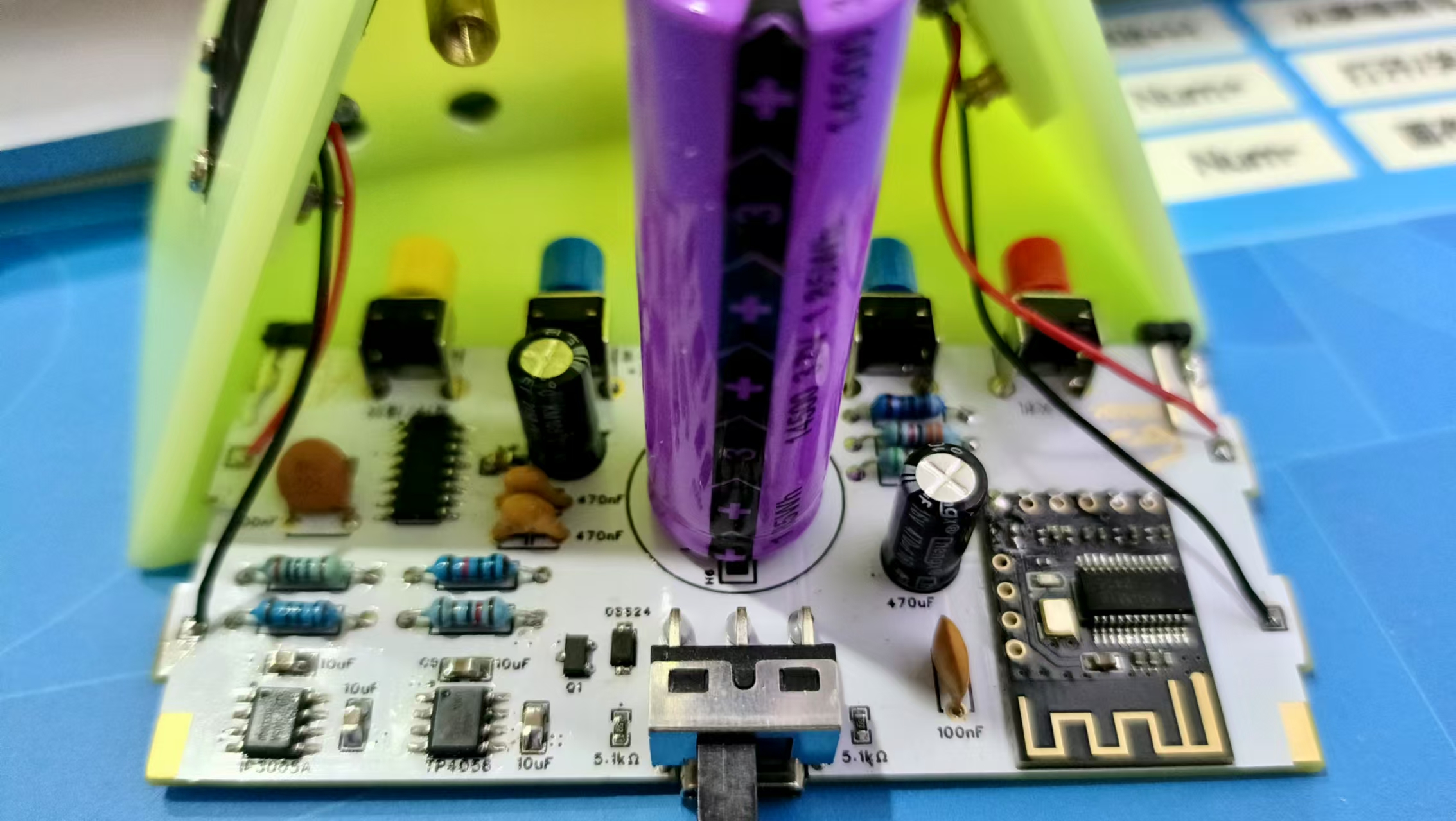
Hardware design
Full Schematic:

Bluetooth circuit:
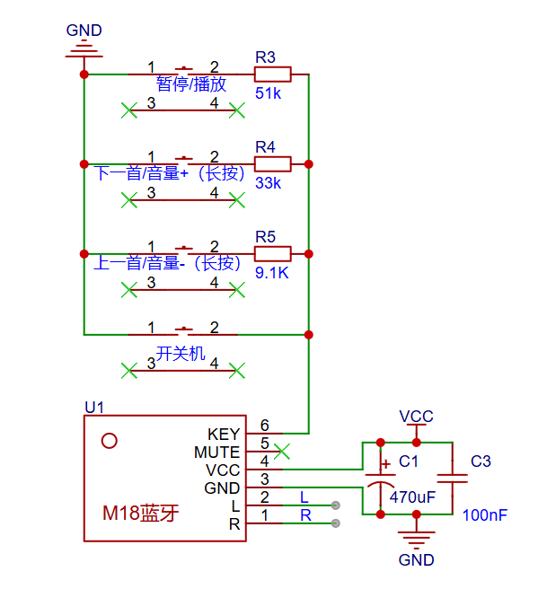
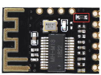
- MH-M18 Bluetooth chip is a low-power Bluetooth design scheme, supporting the latest Bluetooth 5.0 transmission, two-channel stereo lossless playback, after the module is connected to Bluetooth, Bluetooth wireless transmission can be quickly realized, which is very convenient. In an open environment, the Bluetooth connection distance can reach up to 20 meters. It is widely used in all kinds of Bluetooth audio reception, all kinds of audio DIY modification, etc.
- Volume power-off hold function: 100% volume output by default. You can control the volume increase and decrease by pressing and holding the button, if the control volume is less than 15%, the volume output will be 15% after re-powering; If the control volume is greater than 15%, the original volume will remain unchanged after powering it back on.
MH-M18 Module Device Package Information:
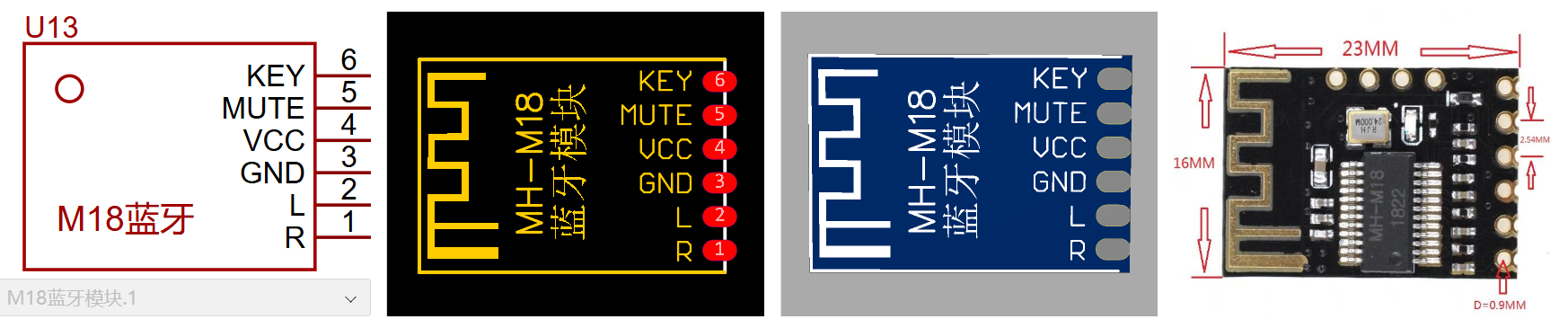
Pin Definition:
|
Pins |
illustrate |
|
KEY |
Button control terminal (4 buttons and 6 functions, additional resistors are required). |
|
MUTE |
Mute control terminal (output high level 3.3V when muted, low level output during playback). |
|
VCC |
The positive pole of the power supply is 5V (a short-circuit diode is required for 3.7V power supply of lithium batteries). |
|
GND |
Power supply aside |
|
L |
Left channel output |
|
R |
Right channel output |
Amplifier circuit:
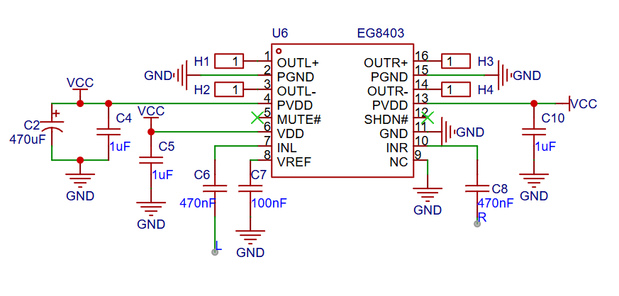
- The EG8403 is a power amplifier IC designed for audio amplification, which can significantly increase the power of audio signals. With its powerful power amplification capabilities, it efficiently drives a wide range of loudspeakers to ensure clear, loud sound. The EG8403 greatly simplifies the circuit design, and its peripheral circuitry is simple, which saves PCB design space and reduces product cost.
Speaker Selection:

- The choice of the 4R3W speaker is just right, the speaker is small, the thickness is appropriate, the assembly is convenient, and the structure is beautiful.
Charging Circuits and Discharge Protection Circuits:
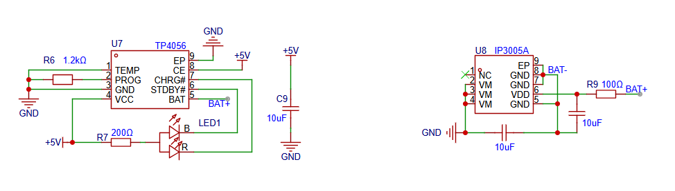
- The TP4056 is a single-cell Li-ion battery CC/CV linear charger with excellent performance. The TP4056 is housed in an ESOP8 package with fewer peripheral components, making it ideal for portable applications and for powering USB power supplies as well as adapter power supplies. The charge current can be determined by the external resistor programming, and the maximum charge current can reach 1000mA.
- The charge current is set using a resistor connected between the PROG pin and ground. The resistor resistance is determined according to the required charging current, and the setting resistor and charging current are calculated using the following formula:

| RPROG(K) | IBAT(mA) |
| 1.2 | 1000 |
| 2.4 | 500 |
| 3.0 | 400 |
| 4.0 | 300 |
| 6.0 | 200 |
| 12 | 100 |
- The TP4056 has two open-drain status indication outputs, CHRG and STDBY. When the charger is in the charging state, the CHRG is pulled to a low level, and the 7-pin is connected to the red light to indicate that it is charging; When the battery is finished, the STDBY is pulled low and the 6-pin blue light indicates that it is fully charged. When the battery is not connected to the charger, the CHRG flashes to indicate that the battery is not installed.
LED Indicator Selection:
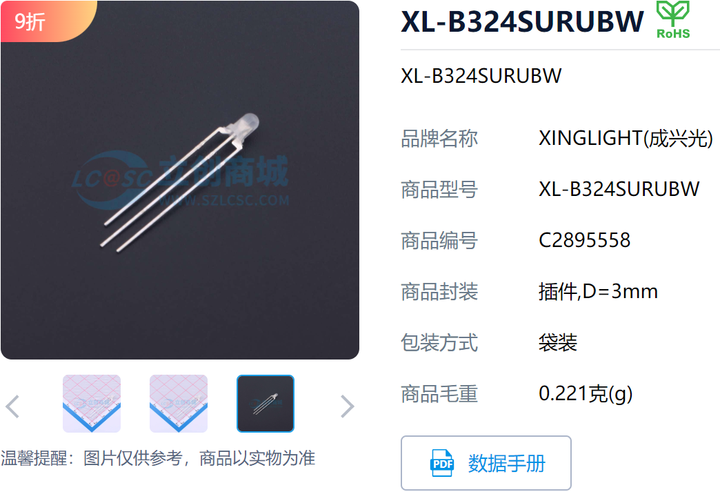
- Select a common anode LED indicator in the Lichuang Mall, and the LED can display a red and blue two-color indication with 3 pins.
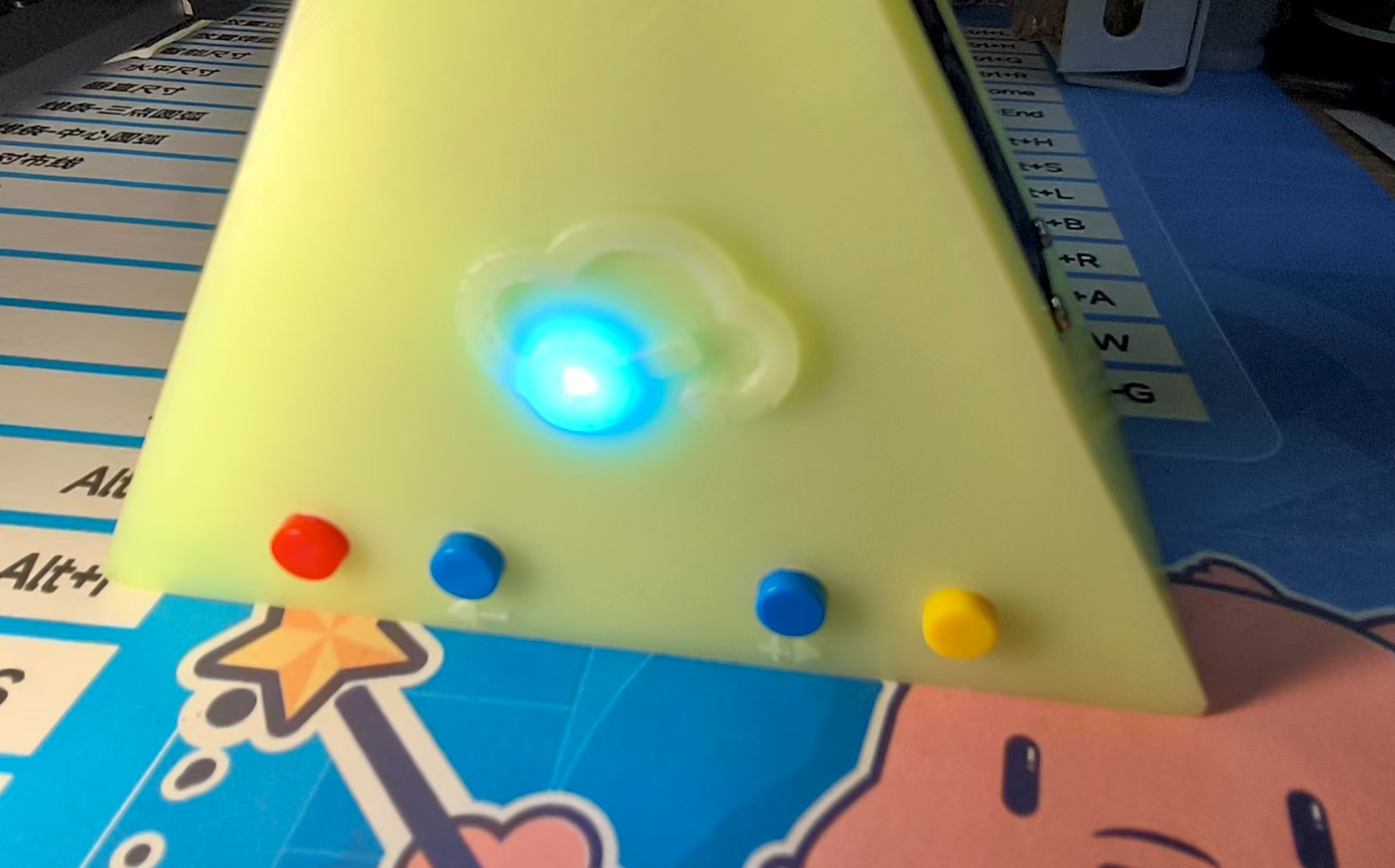
Welding Notes:

- It should be noted that the LED pins should be at this height when soldering, so that the LED light can penetrate through the holes reserved for the 3D shell.
Charging effect:
 |
 |
| Charging, the indicator light is on red | Charging is completed and the indicator light is on blue |
Lithium battery and power switching circuit:
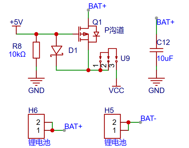
- When there is a battery (3.7V~4.2V) and a power supply interface (5V) in a project at the same time, there is a risk of power backfill. Generally, a power switching circuit will be added to the project, when the power supply interface is not connected, the battery will supply power to the system, and when the power supply interface is connected, the battery will no longer be powered.
- Use diodes, Pmos, and resistors to form a power switching circuit:
When battery power is used, the gate VG potential is close to 0V, VGS < VTH, AND THE PMOS IS ON, AND THE CURRENT FLOWS FROM DRAIN D D TO SOURCE S S DUE TO THE GROUND PULL-DOWN OF THE R8 RESISTOR.
When connected to the 5V power supply of TYP-C, the gate VG potential is close to 5V, VGS > VTH, PMOS As of now, the battery current cannot flow from drain D to source S, and the 5V supply current flows through diode D1 to VCC at the switch to power the system.
- It should be noted that the VGSth of the selected device Pmos should not be too high, otherwise the battery voltage cannot be saturated and turned on, although it can also be used, at this time, the mos tube will heat up seriously and may burn out. In addition, if the battery voltage is higher than the input voltage in this power switching circuit, it cannot be used.
- PMOS (P - type Metal - Oxide - Semiconductor) is a P-type metal-oxide-semiconductor field-effect transistor. It is mainly composed of a source (S), a drain (D), and a gate (G). The schematic diagram of its structure is as follows:
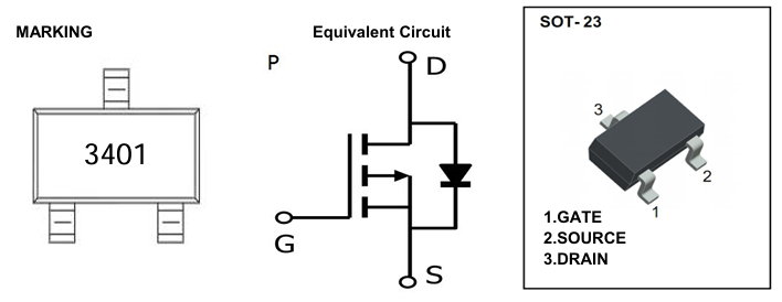
- When the gate voltage VG is lower than the source voltage VS, a conductive channel is formed under the oxide layer below the gate. Specifically, PMOS is turned on when VGS=VG-V S is less than the gate threshold voltage VGSth of PMOS. According to the data sheet of the selected MOS transistor, the gate threshold voltage VGSth is 0.7 V min, 0.9 V typical, and 1.3 V max.
Bluetooth chip precautions:
- Because two power supply methods are used, according to the data sheet of the Bluetooth chip MH-M18, it should be noted when using the power supply of the chip: the default power supply is 5V. If you need to use a 3.7V lithium battery for power, you need to replace the diode (as shown in the figure) with a 0 ohm resistor of 0603, or simply short circuit both ends of the pad. The chip module is powered by 5V by default.
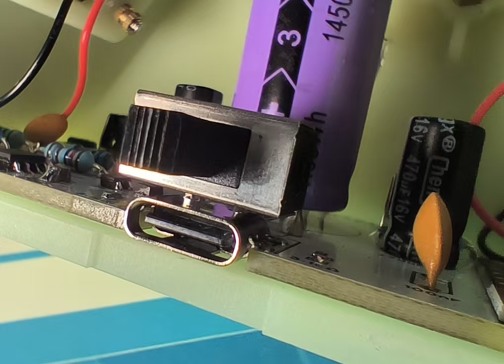
Power switch layout design:
 |
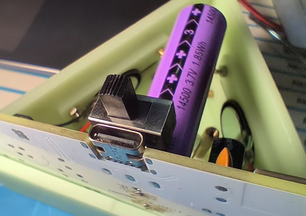 |
- The power switch adopts a stacked design of switch and TYP-C, which makes the structure more compact, symmetrical and beautiful.
Assembly & Fixing:
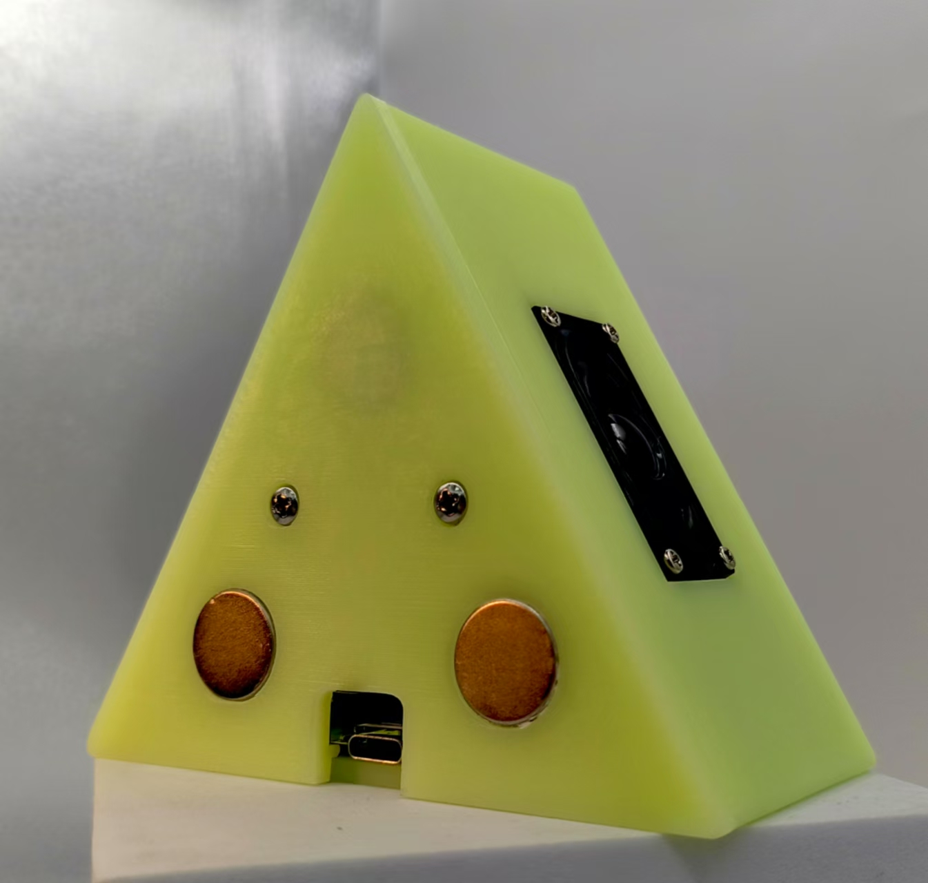
- After the welding is completed, it is assembled into the shell, and the shell is made of Jialichuang 3D printing light-curing resin, which meets the requirements of free proofing.
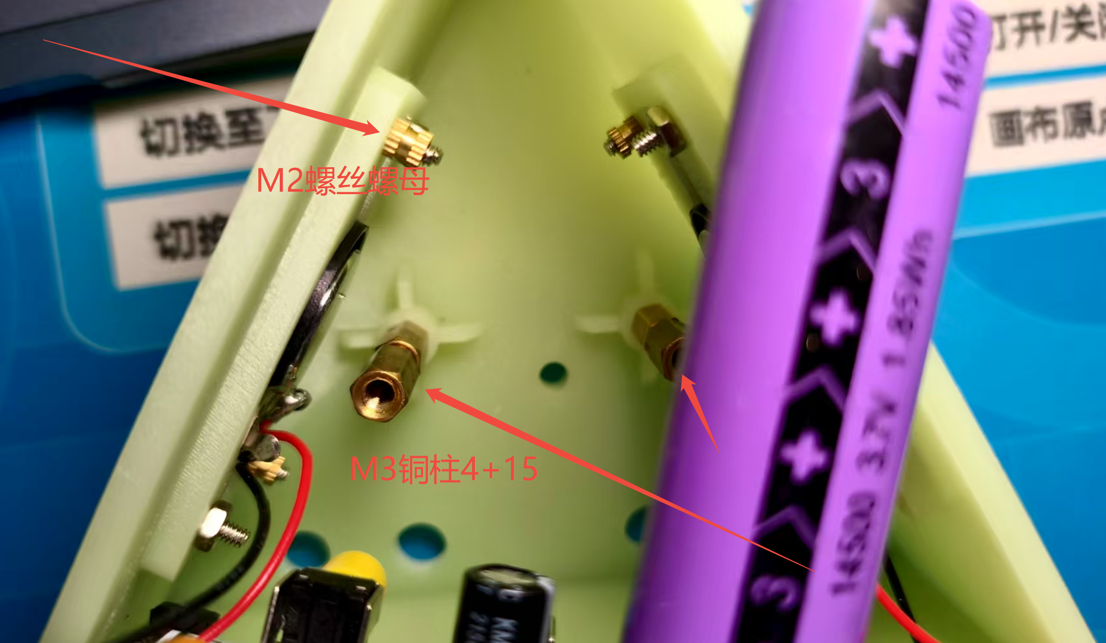
- Speaker fixing can be done with M2*8 screws + any M2 nut.
 |
 |
- To fix the back cover, you need to screw in an M3 copper pillar at the bottom first, and the length of the copper pillar should be as long as possible (M3 * 4 + 30mm or so is recommended), and then use a Phillips screw of appropriate length to fix it, be careful not to tighten it too tightly, the 3D printing structure has low strength and will warp.
Succeed with flying colors
 |
 |
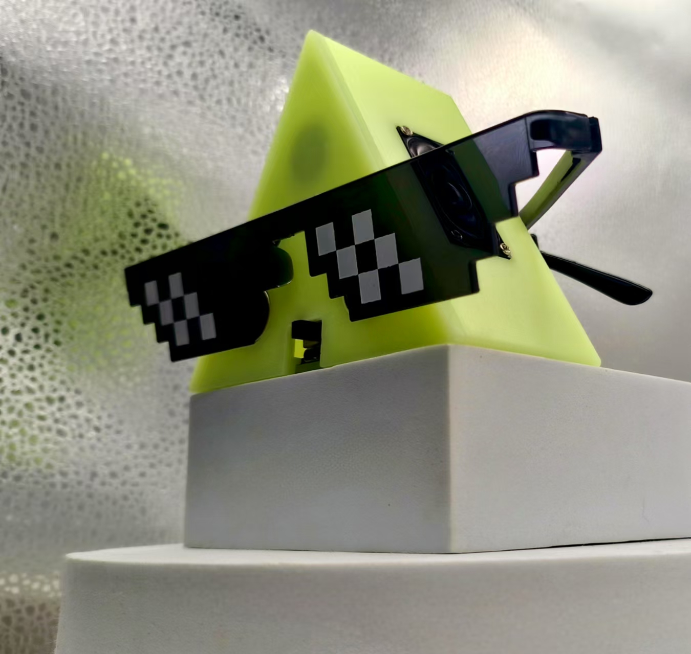
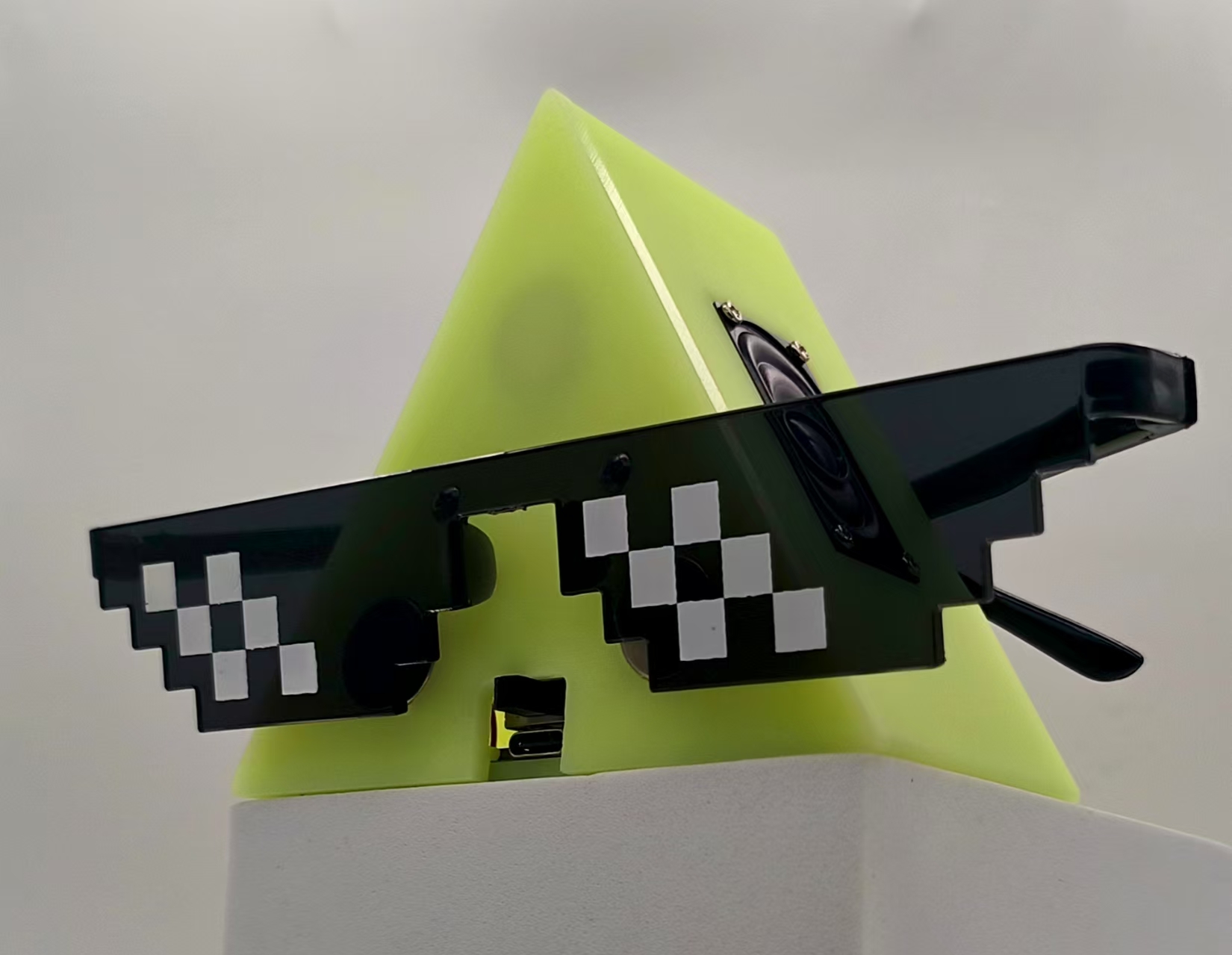
A triangular Bluetooth speaker is complete!!
 |
 |
 |
 |
Designed by 立创EDA课程案例推荐 (from OSHWHub)
Link:https://oshwhub.com/course-examples/huan-yin-san-jiao-m18-lan-ya-yin-xiang
Design Drawing
 Empty
Empty
Comment