

 Completed
Electric solder paste extruder
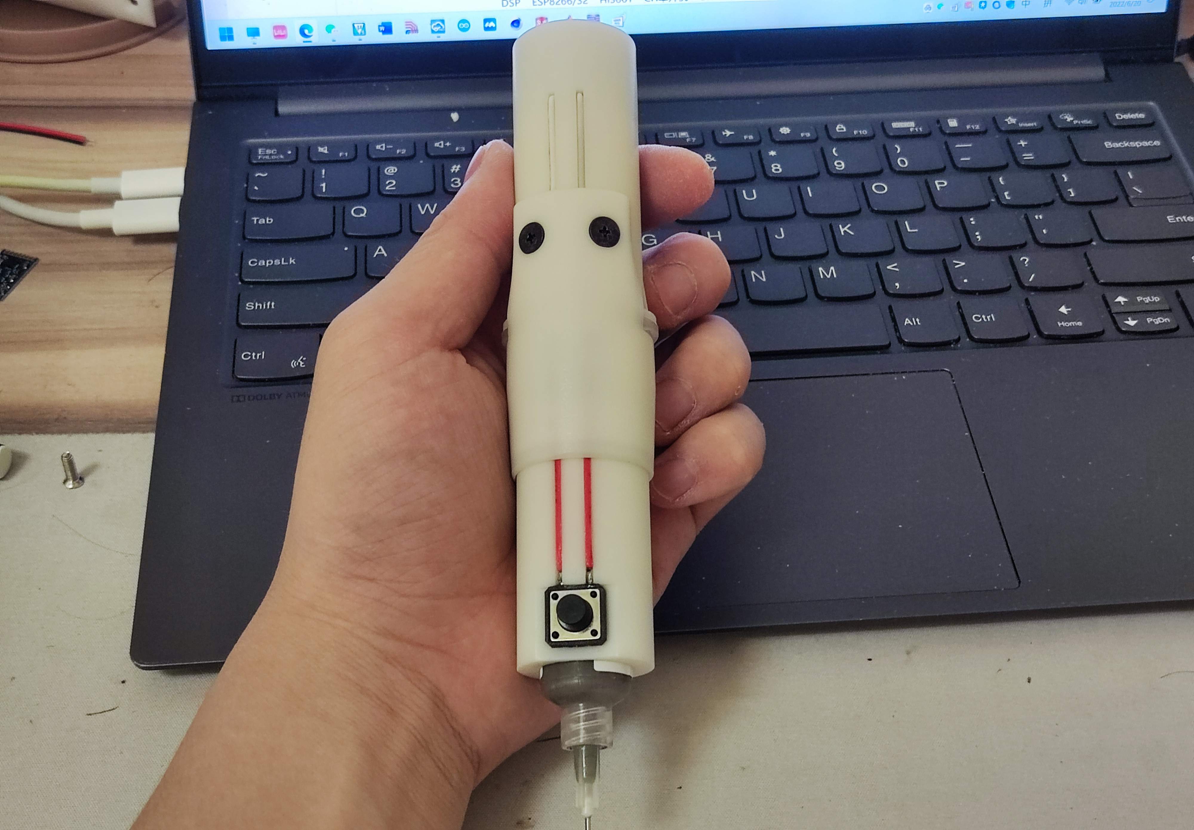
PRO Electric solder paste extruder
License
:GPL 3.0
Description


The extrusion effect is pretty good.
My solder paste is relatively thin. If your solder paste is too dry, you may not be able to squeeze it out.
The motor is an N20 with an M4 screw. The slower the better, the slower the motor is and the more powerful it is.
You also need one M4*10mm nut, four M3*8mm flat head screws, and four M3 nuts.
MCU model STC15W204S, motor driver L9110S.
The size of the large buttons on the front is 12*12mm, and the size of the small buttons on the back is 4.5*4.5mm.
It is recommended that the height of the large buttons be shorter. Mine is too tall and is not easy to use.
The buttons below are connected to the motherboard via pin headers, making it easy to replace the solder paste.


The program code is burned into the microcontroller through stc-isp, and can be burned directly using project.hex in the program file.
When the power is turned on, the light changes forward, which means that the direction of the motor is pushing forward.
Press the big button once to dispense solder paste. The amount of solder paste can be adjusted through the small buttons at the back. The faster the flow lamp is, the greater the amount of solder paste squeezed out at one time.
Press and hold the big button to continuously push forward (it is recommended to press and hold it only when the solder paste has just been changed to make the push rod reach the bottom quickly), and when released, it will pull back a certain distance.
Press the small button on the back at the same time to switch directions, and long press the big button to pull the push rod backward.
Assembly process

Cut off the two pins on the same side of the 12*12 button, solder the other two pins to the wires, insert them into the groove of the front sleeve, and solder them to the pin header. The pin header and wires need to be fixed with glue.


Insert the four M3 nuts into the grooves behind the holes. It is strongly recommended to use glue to fix them . Of course, you can also fix them without fixing them, but it will be a lot more troublesome.
Use glue to fix the DuPont wire female head in the gap, plug the other end of the wire into the hole, and glue the wire in the groove for a more beautiful appearance.
These two wires are soldered to SW1 and GND of the PCB respectively (in any order, it is recommended to solder them when the PCB is installed into the housing later)


Install the 10mmM4 nut into the push rod. It is recommended to fix it with glue. Install the push rod on the motor, then solder the motor pins to the wires and install them into the back seat ( do not fix the motor with glue!!! )


Install the 4.5*4.5 key switch into the square groove of the back cover, fix it with glue, and solder the key to the PCB with wires as shown in the picture.


Weld the motor and DuPont wire to the PCB. Pay attention to the direction of the board and the back cover. The LED on the board should be aligned with the groove on the inner wall of the housing. Install the PCB into the housing and fasten the back cover.


After assembly, simply assemble, power on and test whether the motor wire welding sequence is correct (press and hold the big button to see if the push rod is pushed forward, if pushed in the opposite direction, the motor welding sequence needs to be changed).


After the test is completed, install the syringe (remember to return the push rod to the appropriate position), first install the fixed sleeve, and finally insert the front sleeve.
Designed by 小O和小Q (from OSHWHub)
Design Drawing
Intellectual Property Statement & Reproduction Instructions
This is an open-source hardware project. All intellectual property rights belong to the creator. The project is shared on the platform for learning, communication, and research only; any commercial use is prohibited. If your intellectual property rights are infringed on EasyEDA, please notify us by submitting relevant materials in accordance with the Rules for Complaints and Appeals of IPR Infringement.
Users must independently verify the circuit design and suitability when replicating this project. All risks and consequences are borne by the user, and the platform assumes no liability.
 Empty
Empty
Comment